AT91SAM9G45-EKES Atmel, AT91SAM9G45-EKES Datasheet - Page 242
AT91SAM9G45-EKES
Manufacturer Part Number
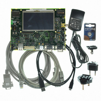
AT91SAM9G45-EKES
Description
KIT EVAL FOR AT91SAM9G45
Manufacturer
Atmel
Series
AT91SAM Smart ARMr
Type
MCUr
Datasheets
1.AT91SAM9G45-EKES.pdf
(56 pages)
2.AT91SAM9G45-EKES.pdf
(1218 pages)
3.AT91SAM9G45-EKES.pdf
(66 pages)
Specifications of AT91SAM9G45-EKES
Contents
Board
Processor To Be Evaluated
SAM9G45
Data Bus Width
32 bit
Interface Type
I2C, SPI, UART
Maximum Operating Temperature
+ 50 C
Minimum Operating Temperature
- 10 C
Operating Supply Voltage
1.8 V to 3.3 V
For Use With/related Products
AT91SAM9G45
Lead Free Status / RoHS Status
Lead free / RoHS Compliant
Other names
Q4626953


To comply with SDRAM timing parameters, additional clock cycles are inserted between pre-
charge/active (Trp) commands and active/read (Trcd) commands. The DDRSDRC supports a
cas latency of two, two and half, and three (2 or 3 clocks delay). During this delay, the controller
uses internal signals to anticipate the next access and improve the performance of the control-
ler. Depending on the latency(2/3), the DDRSDRC anticipates 2 or 3 read accesses. In the case
of burst of specified length, accesses are not anticipated, but if the burst is broken (border, busy
mode, etc.), the next access is treated as an incrementing burst of unspecified length, and in
function of the latency(2/3), the DDRSDRC anticipates 2 or 3 read accesses.
For a definition of timing parameters, refer to
Section 22.7.3 “DDRSDRC Configuration Register”
on page
262.
Read accesses to the SDRAM are burst oriented and the burst length is programmed to 8. It
determines the maximum number of column locations that can be accessed for a given read
command. When the read command is issued, 8 columns are selected. All accesses for that
burst take place within these eight columns, meaning that the burst wraps within these 8 col-
umns if the boundary is reached. These 8 columns are selected by addr[13:3]; addr[2:0] is used
to select the starting location within the block.
In the case of incrementing burst (INCR/INCR4/INCR8/INCR16), the addresses can cross the
16-byte boundary of the SDRAM device. For example, when a transfer (INCR4) starts at
address 0x0C, the next access is 0x10, but since the burst length is programmed to 8, the next
access is 0x00. Since the boundary is reached, the burst wraps. The DDRSDRC takes into
account this feature of the SDRAM device. In the case of DDR-SDRAM devices, transfers start
at address 0x04/0x08/0x0C. In the case of SDR-SDRAM devices, transfers start at address
0x14/0x18/0x1C. Two read commands are issued to avoid wrapping when the boundary is
reached. The last read command may generate additional reading (1 read cmd = 4 DDR words
or 1 read cmd = 8 SDR words).
To avoid additional reading, it is possible to use the burst stop command to truncate the read
burst and to decrease power consumption.
AT91SAM9G45
242
6438F–ATARM–21-Jun-10
Related parts for AT91SAM9G45-EKES
Image
Part Number
Description
Manufacturer
Datasheet
Request
R

Part Number:
Description:
MCU ARM9 64K SRAM 144-LFBGA
Manufacturer:
Atmel
Datasheet:

Part Number:
Description:
IC ARM7 MCU FLASH 256K 100LQFP
Manufacturer:
Atmel
Datasheet:

Part Number:
Description:
IC ARM9 MPU 217-LFBGA
Manufacturer:
Atmel
Datasheet:
Part Number:
Description:
MCU ARM9 ULTRA LOW PWR 217-LFBGA
Manufacturer:
Atmel
Datasheet:

Part Number:
Description:
MCU ARM9 324-TFBGA
Manufacturer:
Atmel
Datasheet:
Part Number:
Description:
IC MCU ARM9 SAMPLING 217CBGA
Manufacturer:
Atmel
Datasheet:
Part Number:
Description:
IC ARM9 MCU 217-LFBGA
Manufacturer:
Atmel
Datasheet:

Part Number:
Description:
IC ARM9 MCU 208-PQFP
Manufacturer:
Atmel
Datasheet:
Part Number:
Description:
MCU ARM 512K HS FLASH 100-LQFP
Manufacturer:
Atmel
Datasheet:

Part Number:
Description:
MCU ARM 512K HS FLASH 100-TFBGA
Manufacturer:
Atmel
Datasheet:
Part Number:
Description:
IC ARM9 MCU 200 MHZ 324-TFBGA
Manufacturer:
Atmel
Datasheet:

Part Number:
Description:
IC ARM MCU 16BIT 128K 256BGA
Manufacturer:
Atmel
Datasheet:

Part Number:
Description:
IC ARM7 MCU 32BIT 128K 64LQFP
Manufacturer:
Atmel
Datasheet:

Part Number:
Description:
IC ARM7 MCU FLASH 256K 128-LQFP
Manufacturer:
Atmel
Datasheet:
Part Number:
Description:
IC ARM7 MCU FLASH 512K 128-LQFP
Manufacturer:
Atmel
Datasheet: