AT91SAM9G45-EKES Atmel, AT91SAM9G45-EKES Datasheet - Page 1189
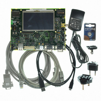
AT91SAM9G45-EKES
Manufacturer Part Number
AT91SAM9G45-EKES
Description
KIT EVAL FOR AT91SAM9G45
Manufacturer
Atmel
Series
AT91SAM Smart ARMr
Type
MCUr
Datasheets
1.AT91SAM9G45-EKES.pdf
(56 pages)
2.AT91SAM9G45-EKES.pdf
(1218 pages)
3.AT91SAM9G45-EKES.pdf
(66 pages)
Specifications of AT91SAM9G45-EKES
Contents
Board
Processor To Be Evaluated
SAM9G45
Data Bus Width
32 bit
Interface Type
I2C, SPI, UART
Maximum Operating Temperature
+ 50 C
Minimum Operating Temperature
- 10 C
Operating Supply Voltage
1.8 V to 3.3 V
For Use With/related Products
AT91SAM9G45
Lead Free Status / RoHS Status
Lead free / RoHS Compliant
Other names
Q4626953


Figure 46-25. SPI Slave Mode - NPCS Timings
Table 46-46. UART SPI Timings with 3.3V Peripheral Supply
Notes:
6438F–ATARM–21-Jun-10
Symbol
SPI
SPI
SPI
SPI
SPI
SPI
SPI
SPI
SPI
SPI
SPI
SPI
SPI
SPI
SPI
SPI
SPI
0
1
2
3
4
5
6
7
8
9
10
11
12
13
14
15
16
1. For output signals, Min and Max access time must be extracted. The Min access time is the time between the SPCK rising or
falling edge and the signal change. The Max access time is the time between the SPCK rising or falling edge and the signal
stabilization.
Parameter
SPCK Period
Input Data Setup Time
Input Data Hold Time
Chip Select Active to Serial Clock
Output Data Setup Time
Serial Clock to Chip Select Inactive
SPCK falling to MISO
MOSI Setup time before SPCK rises
MOSI Hold time after SPCK rises
SPCK rising to MISO
MOSI Setup time before SPCK falls
MOSI Hold time after SPCK falls
NPCS0 setup to SPCK rising
NPCS0 hold after SPCK falling
NPCS0 setup to SPCK falling
NPCS0 hold after SPCK rising
NPCS0 falling to MISO valid
Figure 46-9
(CPOL = 0)
(CPOL = 1)
MISO
SPCK
SPCK
illustrates Min and Max accesses for SPI2. The same applies to SPI5, SPI6, SPI9.
SPI
SPI
SPI
16
12
14
SPI
6
SPI
9
Master Mode
Slave Mode
Cond
13.8
4.7
17.2
10.3
10.7
Min
7.5
0.4
2.0
2.0
2.9
0
0
(1)
(1)
SPI
SPI
15
13
AT91SAM9G45
16.9
17.1
Max
16.0
-0.3
3.5
0.2
(1)
(1)
Units
ns
ns
ns
ns
ns
ns
ns
ns
ns
ns
ns
ns
ns
ns
ns
ns
ns
1189
Related parts for AT91SAM9G45-EKES
Image
Part Number
Description
Manufacturer
Datasheet
Request
R

Part Number:
Description:
MCU ARM9 64K SRAM 144-LFBGA
Manufacturer:
Atmel
Datasheet:

Part Number:
Description:
IC ARM7 MCU FLASH 256K 100LQFP
Manufacturer:
Atmel
Datasheet:

Part Number:
Description:
IC ARM9 MPU 217-LFBGA
Manufacturer:
Atmel
Datasheet:
Part Number:
Description:
MCU ARM9 ULTRA LOW PWR 217-LFBGA
Manufacturer:
Atmel
Datasheet:

Part Number:
Description:
MCU ARM9 324-TFBGA
Manufacturer:
Atmel
Datasheet:
Part Number:
Description:
IC MCU ARM9 SAMPLING 217CBGA
Manufacturer:
Atmel
Datasheet:
Part Number:
Description:
IC ARM9 MCU 217-LFBGA
Manufacturer:
Atmel
Datasheet:

Part Number:
Description:
IC ARM9 MCU 208-PQFP
Manufacturer:
Atmel
Datasheet:
Part Number:
Description:
MCU ARM 512K HS FLASH 100-LQFP
Manufacturer:
Atmel
Datasheet:

Part Number:
Description:
MCU ARM 512K HS FLASH 100-TFBGA
Manufacturer:
Atmel
Datasheet:
Part Number:
Description:
IC ARM9 MCU 200 MHZ 324-TFBGA
Manufacturer:
Atmel
Datasheet:

Part Number:
Description:
IC ARM MCU 16BIT 128K 256BGA
Manufacturer:
Atmel
Datasheet:

Part Number:
Description:
IC ARM7 MCU 32BIT 128K 64LQFP
Manufacturer:
Atmel
Datasheet:

Part Number:
Description:
IC ARM7 MCU FLASH 256K 128-LQFP
Manufacturer:
Atmel
Datasheet:
Part Number:
Description:
IC ARM7 MCU FLASH 512K 128-LQFP
Manufacturer:
Atmel
Datasheet: