AT91SAM9G45-EKES Atmel, AT91SAM9G45-EKES Datasheet - Page 1063
AT91SAM9G45-EKES
Manufacturer Part Number
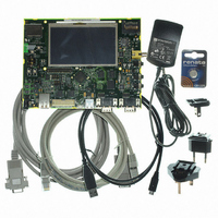
AT91SAM9G45-EKES
Description
KIT EVAL FOR AT91SAM9G45
Manufacturer
Atmel
Series
AT91SAM Smart ARMr
Type
MCUr
Datasheets
1.AT91SAM9G45-EKES.pdf
(56 pages)
2.AT91SAM9G45-EKES.pdf
(1218 pages)
3.AT91SAM9G45-EKES.pdf
(66 pages)
Specifications of AT91SAM9G45-EKES
Contents
Board
Processor To Be Evaluated
SAM9G45
Data Bus Width
32 bit
Interface Type
I2C, SPI, UART
Maximum Operating Temperature
+ 50 C
Minimum Operating Temperature
- 10 C
Operating Supply Voltage
1.8 V to 3.3 V
For Use With/related Products
AT91SAM9G45
Lead Free Status / RoHS Status
Lead free / RoHS Compliant
Other names
Q4626953


43.7.4
43.7.5
43.7.5.1
43.7.5.2
43.7.5.3
1063
AT91SAM9G45
Variable Sample Rate
Power Management
Powering Down the AC-Link
Waking up the AC-link
Wake-up Triggered by the AC97 Controller
The problem of variable sample rate can be summarized by a simple example. When passing a
44.1 kHz stream across the AC-link, for every 480 audio output frames that are sent across, 441
of them must contain valid sample data. The new AC97 standard approach calls for the addition
of “on-demand” slot request flags. The AC97 Codec examines its sample rate control register,
the state of its FIFOs, and the incoming SDATA_OUT tag bits (slot 0) of each output frame and
then determines which SLOTREQ bits to set active (low). These bits are passed from the AC97
Codec to the AC97 Controller in slot 1/SLOTREQ in every audio input frame. Each time the
AC97 controller sees one or more of the newly defined slot request flags set active (low) in a
given audio input frame, it must pass along the next PCM sample for the corresponding slot(s) in
the AC-link output frame that immediately follows.
The variable Sample Rate mode is enabled by performing the following steps:
Slot 1 of the input frame is automatically interpreted as SLOTREQ signaling bits. The AC97 Con-
troller will automatically fill the active slots according to both SLOTREQ and AC97C_OCA
register in the next transmitted frame.
The AC97 Codecs can be placed in low power mode. The application can bring AC97 Codec to
a power down state by performing sequential writes to AC97 Codec powerdown register. Both
the bit clock (clock delivered by AC97 Codec, AC97CK) and the input line (AC97RX) are held at
a logic low voltage level. This puts AC97 Codec in power down state while all its registers are
still holding current values. Without the bit clock, the AC-link is completely in a power down
state.
The AC97 Controller should not attempt to play or capture audio data until it has awakened
AC97 Codec.
To set the AC97 Codec in low power mode, the PR4 bit in the AC97 Codec powerdown register
(Codec address 0x26) must be set to 1. Then the primary Codec drives both AC97CK and
AC97RX to a low logic voltage level.
The following operations must be done to put AC97 Codec in low power mode:
At this point AC97 Codec is in low power mode.
There are two methods to bring the AC-link out of low power mode. Regardless of the method, it
is always the AC97 Controller that performs the wake-up.
The AC97 Controller can wake up the AC97 Codec by issuing either a cold or a warm reset.
• Setting the VRA bit in the AC97 Controller Mode Register (AC97C_MR).
• Enable Variable Rate mode in the AC97 Codec by performing a transfer on the Codec
• Disable Channel A clearing CEN field in the AC97C_CAMR register.
• Disable Channel B clearing CEN field in the AC97C_CBMR register.
• Write 0x2680 value in the AC97C_COTHR register.
• Poll the TXEMPTY flag in AC97C_CxSR registers for the 2 channels.
channel.
6438F–ATARM–21-Jun-10
Related parts for AT91SAM9G45-EKES
Image
Part Number
Description
Manufacturer
Datasheet
Request
R

Part Number:
Description:
MCU ARM9 64K SRAM 144-LFBGA
Manufacturer:
Atmel
Datasheet:

Part Number:
Description:
IC ARM7 MCU FLASH 256K 100LQFP
Manufacturer:
Atmel
Datasheet:

Part Number:
Description:
IC ARM9 MPU 217-LFBGA
Manufacturer:
Atmel
Datasheet:
Part Number:
Description:
MCU ARM9 ULTRA LOW PWR 217-LFBGA
Manufacturer:
Atmel
Datasheet:

Part Number:
Description:
MCU ARM9 324-TFBGA
Manufacturer:
Atmel
Datasheet:
Part Number:
Description:
IC MCU ARM9 SAMPLING 217CBGA
Manufacturer:
Atmel
Datasheet:
Part Number:
Description:
IC ARM9 MCU 217-LFBGA
Manufacturer:
Atmel
Datasheet:

Part Number:
Description:
IC ARM9 MCU 208-PQFP
Manufacturer:
Atmel
Datasheet:
Part Number:
Description:
MCU ARM 512K HS FLASH 100-LQFP
Manufacturer:
Atmel
Datasheet:

Part Number:
Description:
MCU ARM 512K HS FLASH 100-TFBGA
Manufacturer:
Atmel
Datasheet:
Part Number:
Description:
IC ARM9 MCU 200 MHZ 324-TFBGA
Manufacturer:
Atmel
Datasheet:

Part Number:
Description:
IC ARM MCU 16BIT 128K 256BGA
Manufacturer:
Atmel
Datasheet:

Part Number:
Description:
IC ARM7 MCU 32BIT 128K 64LQFP
Manufacturer:
Atmel
Datasheet:

Part Number:
Description:
IC ARM7 MCU FLASH 256K 128-LQFP
Manufacturer:
Atmel
Datasheet:
Part Number:
Description:
IC ARM7 MCU FLASH 512K 128-LQFP
Manufacturer:
Atmel
Datasheet: