AT91SAM9G45-EKES Atmel, AT91SAM9G45-EKES Datasheet - Page 939
AT91SAM9G45-EKES
Manufacturer Part Number
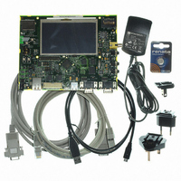
AT91SAM9G45-EKES
Description
KIT EVAL FOR AT91SAM9G45
Manufacturer
Atmel
Series
AT91SAM Smart ARMr
Type
MCUr
Datasheets
1.AT91SAM9G45-EKES.pdf
(56 pages)
2.AT91SAM9G45-EKES.pdf
(1218 pages)
3.AT91SAM9G45-EKES.pdf
(66 pages)
Specifications of AT91SAM9G45-EKES
Contents
Board
Processor To Be Evaluated
SAM9G45
Data Bus Width
32 bit
Interface Type
I2C, SPI, UART
Maximum Operating Temperature
+ 50 C
Minimum Operating Temperature
- 10 C
Operating Supply Voltage
1.8 V to 3.3 V
For Use With/related Products
AT91SAM9G45
Lead Free Status / RoHS Status
Lead free / RoHS Compliant
Other names
Q4626953


40.6.4
40.6.5
40.7
40.7.1
6438F–ATARM–21-Jun-10
Touch Screen
Startup Time
Sample and Hold Time
Resistive Touch Screen Principles
The Touch Screen ADC has a minimal Startup Time when it exits the Sleep Mode. As the ADC
Clock depends on the application, the user has to program the field STARTUP in the
Mode
conversion of the sequence.
The field STARTUP can define a Startup Time between 8 and 1024 ADC Clock cycles by steps
of 8.
The user must assure that ADC Startup Time given in the section “Electrical Characteristics” is
covered by this wait time.
In the same way, a minimal Sample and Hold Time is necessary for the TSADCC to guarantee
the best converted final value between selection of two channels. This time depends on the input
impedance of the analog input, but also on the output impedance of the driver providing the sig-
nal to the analog input, as there is no input buffer amplifier.
The Sample and Hold time has to be programmed through the bitfields SHTIM in the
Mode Register”
The field SHTIM defines the number of ADC Clock cycles for an analog input, while the field
TSSHTIM defines the number of ADC Clock cycles for a Touch Screen input.
These both fields can define a Sample and Hold time between 1 and 16 ADC Clock cycles.
The field TSSHTIM defines also the time the power switches of the Touch Screen are closed
when the TSADCC performs a conversion for the Touch Screen.
A resistive touch screen is based on two resistive films, each one being fitted with a pair of elec-
trodes, placed at the top and bottom on one film, and on the right and left on the other. Between
the two, there is a layer that acts as an insulator, but also enables contact when you press the
screen. This is illustrated in
The TSADC controller has the ability to perform without external components:
• Position Measurement
• Pressure Measurement
• Pen Detection
Register”, which defines how many ADC Clock cycles to wait before performing the first
and TSSHTIM in the
Figure
40-2.
“TSADCC Touch Screen
Register”.
AT91SAM9G45
“TSADCC
“TSADCC
939
Related parts for AT91SAM9G45-EKES
Image
Part Number
Description
Manufacturer
Datasheet
Request
R

Part Number:
Description:
MCU ARM9 64K SRAM 144-LFBGA
Manufacturer:
Atmel
Datasheet:

Part Number:
Description:
IC ARM7 MCU FLASH 256K 100LQFP
Manufacturer:
Atmel
Datasheet:

Part Number:
Description:
IC ARM9 MPU 217-LFBGA
Manufacturer:
Atmel
Datasheet:
Part Number:
Description:
MCU ARM9 ULTRA LOW PWR 217-LFBGA
Manufacturer:
Atmel
Datasheet:

Part Number:
Description:
MCU ARM9 324-TFBGA
Manufacturer:
Atmel
Datasheet:
Part Number:
Description:
IC MCU ARM9 SAMPLING 217CBGA
Manufacturer:
Atmel
Datasheet:
Part Number:
Description:
IC ARM9 MCU 217-LFBGA
Manufacturer:
Atmel
Datasheet:

Part Number:
Description:
IC ARM9 MCU 208-PQFP
Manufacturer:
Atmel
Datasheet:
Part Number:
Description:
MCU ARM 512K HS FLASH 100-LQFP
Manufacturer:
Atmel
Datasheet:

Part Number:
Description:
MCU ARM 512K HS FLASH 100-TFBGA
Manufacturer:
Atmel
Datasheet:
Part Number:
Description:
IC ARM9 MCU 200 MHZ 324-TFBGA
Manufacturer:
Atmel
Datasheet:

Part Number:
Description:
IC ARM MCU 16BIT 128K 256BGA
Manufacturer:
Atmel
Datasheet:

Part Number:
Description:
IC ARM7 MCU 32BIT 128K 64LQFP
Manufacturer:
Atmel
Datasheet:

Part Number:
Description:
IC ARM7 MCU FLASH 256K 128-LQFP
Manufacturer:
Atmel
Datasheet:
Part Number:
Description:
IC ARM7 MCU FLASH 512K 128-LQFP
Manufacturer:
Atmel
Datasheet: