OM13006,598 NXP Semiconductors, OM13006,598 Datasheet - Page 82
OM13006,598
Manufacturer Part Number
OM13006,598
Description
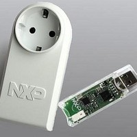
BOARD EVAL EM773 METER EU PLUG
Manufacturer
NXP Semiconductors
Type
Other Power Managementr
Specifications of OM13006,598
Design Resources
Plug Meter Schematics, Gerber Files USB Dongle Schematics, Gerber Files
Main Purpose
Power Management, Energy/Power Meter
Embedded
Yes, MCU, 32-Bit
Utilized Ic / Part
EM773FHN33,551
Interface Type
USB
Maximum Operating Temperature
+ 150 C
Operating Supply Voltage
1.8 V to 3.6 V
Product
Power Management Development Tools
Lead Free Status / RoHS Status
Lead free / RoHS Compliant
Primary Attributes
-
Secondary Attributes
-
Lead Free Status / Rohs Status
Lead free / RoHS Compliant
For Use With/related Products
EM773, OL2381
Other names
568-6681


NXP Semiconductors
UM10415
User manual
Fig 9.
UART1 Rx
UART1 Rx
UART1 Rx
FIFO read
FIFO level
RTS1 pin
Auto-RTS Functional Timing
9.6.8.1.2 Auto-CTS
start
N-1
byte N
Example: Suppose the UART operating in type ‘550 mode has the trigger level in U0FCR
set to 0x2, then, if Auto-RTS is enabled, the UART will deassert the RTS output as soon
as the receive FIFO contains 8 bytes
reasserted as soon as the receive FIFO hits the previous trigger level: 4 bytes.
The Auto-CTS function is enabled by setting the CTSen bit. If Auto-CTS is enabled, the
transmitter circuitry in the U0TSR module checks CTS input before sending the next data
byte. When CTS is active (low), the transmitter sends the next byte. To stop the
transmitter from sending the following byte, CTS must be released before the middle of
the last stop bit that is currently being sent. In Auto-CTS mode, a change of the CTS
signal does not trigger a modem status interrupt unless the CTS Interrupt Enable bit is set,
Delta CTS bit in the U0MSR will be set though.
generating a Modem Status interrupt.
Table 100. Modem status interrupt generation
The auto-CTS function reduces interrupts to the host system. When flow control is
enabled, a CTS state change does not trigger host interrupts because the device
automatically controls its own transmitter. Without Auto-CTS, the transmitter sends any
data present in the transmit FIFO and a receiver overrun error can result.
illustrates the Auto-CTS functional timing.
Enable
modem
status
interrupt
(U0ER[3])
0
1
1
1
1
1
1
1
1
stop
start
N
CTSen
(U0MCR[7])
x
0
0
0
1
1
1
1
1
All information provided in this document is subject to legal disclaimers.
bits0..7
N-1
Rev. 1 — 10 September 2010
Chapter 9: EM773 Universal Asynchronous Transmitter (UART)
CTS
interrupt
enable
(U0IER[7])
x
x
x
x
0
0
1
1
1
stop
N-2
N-1
(Table 97 on page
Delta CTS
(U0MSR[0])
x
0
1
x
x
x
0
1
x
N-2
Table 100
Delta DCD or trailing edge
RI or
Delta DSR (U0MSR[3] or
U0MSR[2] or U0MSR[1])
x
0
x
1
0
1
0
x
1
M+2
79). The RTS output will be
lists the conditions for
M+1
M
start
UM10415
© NXP B.V. 2010. All rights reserved.
Figure 10
bits0..7
M-1
Modem
status
interrupt
No
No
Yes
Yes
No
Yes
No
Yes
Yes
82 of 310
stop
Related parts for OM13006,598
Image
Part Number
Description
Manufacturer
Datasheet
Request
R

Part Number:
Description:
NXP Semiconductors designed the LPC2420/2460 microcontroller around a 16-bit/32-bitARM7TDMI-S CPU core with real-time debug interfaces that include both JTAG andembedded trace
Manufacturer:
NXP Semiconductors
Datasheet:

Part Number:
Description:
NXP Semiconductors designed the LPC2458 microcontroller around a 16-bit/32-bitARM7TDMI-S CPU core with real-time debug interfaces that include both JTAG andembedded trace
Manufacturer:
NXP Semiconductors
Datasheet:
Part Number:
Description:
NXP Semiconductors designed the LPC2468 microcontroller around a 16-bit/32-bitARM7TDMI-S CPU core with real-time debug interfaces that include both JTAG andembedded trace
Manufacturer:
NXP Semiconductors
Datasheet:
Part Number:
Description:
NXP Semiconductors designed the LPC2470 microcontroller, powered by theARM7TDMI-S core, to be a highly integrated microcontroller for a wide range ofapplications that require advanced communications and high quality graphic displays
Manufacturer:
NXP Semiconductors
Datasheet:
Part Number:
Description:
NXP Semiconductors designed the LPC2478 microcontroller, powered by theARM7TDMI-S core, to be a highly integrated microcontroller for a wide range ofapplications that require advanced communications and high quality graphic displays
Manufacturer:
NXP Semiconductors
Datasheet:
Part Number:
Description:
The Philips Semiconductors XA (eXtended Architecture) family of 16-bit single-chip microcontrollers is powerful enough to easily handle the requirements of high performance embedded applications, yet inexpensive enough to compete in the market for hi
Manufacturer:
NXP Semiconductors
Datasheet:
Part Number:
Description:
The XA-S3 device is a member of Philips Semiconductors? XA(eXtended Architecture) family of high performance 16-bitsingle-chip microcontrollers
Manufacturer:
NXP Semiconductors
Datasheet:

Part Number:
Description:
The NXP BlueStreak LH75401/LH75411 family consists of two low-cost 16/32-bit System-on-Chip (SoC) devices
Manufacturer:
NXP Semiconductors
Datasheet:
Part Number:
Description:
The NXP LPC3130/3131 combine an 180 MHz ARM926EJ-S CPU core, high-speed USB2
Manufacturer:
NXP Semiconductors
Datasheet:
Part Number:
Description:
The NXP LPC3141 combine a 270 MHz ARM926EJ-S CPU core, High-speed USB 2
Manufacturer:
NXP Semiconductors
Part Number:
Description:
The NXP LPC3143 combine a 270 MHz ARM926EJ-S CPU core, High-speed USB 2
Manufacturer:
NXP Semiconductors

Part Number:
Description:
The NXP LPC3152 combines an 180 MHz ARM926EJ-S CPU core, High-speed USB 2
Manufacturer:
NXP Semiconductors
Part Number:
Description:
The NXP LPC3154 combines an 180 MHz ARM926EJ-S CPU core, High-speed USB 2
Manufacturer:
NXP Semiconductors

Part Number:
Description:
Standard level N-channel enhancement mode Field-Effect Transistor (FET) in a plastic package using NXP High-Performance Automotive (HPA) TrenchMOS technology
Manufacturer:
NXP Semiconductors
Datasheet: