OM13006,598 NXP Semiconductors, OM13006,598 Datasheet - Page 220
OM13006,598
Manufacturer Part Number
OM13006,598
Description
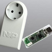
BOARD EVAL EM773 METER EU PLUG
Manufacturer
NXP Semiconductors
Type
Other Power Managementr
Specifications of OM13006,598
Design Resources
Plug Meter Schematics, Gerber Files USB Dongle Schematics, Gerber Files
Main Purpose
Power Management, Energy/Power Meter
Embedded
Yes, MCU, 32-Bit
Utilized Ic / Part
EM773FHN33,551
Interface Type
USB
Maximum Operating Temperature
+ 150 C
Operating Supply Voltage
1.8 V to 3.6 V
Product
Power Management Development Tools
Lead Free Status / RoHS Status
Lead free / RoHS Compliant
Primary Attributes
-
Secondary Attributes
-
Lead Free Status / Rohs Status
Lead free / RoHS Compliant
For Use With/related Products
EM773, OL2381
Other names
568-6681


NXP Semiconductors
UM10415
User manual
18.5.7 Compare <address1> <address2> <no of bytes> (IAP)
18.5.8 Reinvoke ISP (IAP)
18.5.9 ReadUID (IAP)
Table 209. IAP Compare command
Table 210. IAP Reinvoke ISP
Table 211. IAP ReadUID command
Command
Input
Return Code
Result
Description
Command
Input
Return Code
Result
Description
Command
Input
Return Code
Result
Description
Compare
Command code: 5610
Param0(DST): Starting flash or RAM address of data bytes to be compared. This
address should be a word boundary.
Param1(SRC): Starting flash or RAM address of data bytes to be compared. This
address should be a word boundary.
Param2: Number of bytes to be compared; should be a multiple of 4.
CMD_SUCCESS |
COMPARE_ERROR |
COUNT_ERROR (Byte count is not a multiple of 4) |
ADDR_ERROR |
ADDR_NOT_MAPPED
Result0: Offset of the first mismatch if the Status Code is COMPARE_ERROR.
This command is used to compare the memory contents at two locations.
The result may not be correct when the source or destination includes any
of the first 512 bytes starting from address zero. The first 512 bytes can be
re-mapped to RAM.
Compare
Command code: 5710
None
None.
This command is used to invoke the bootloader in ISP mode. It maps boot
vectors, sets PCLK = CCLK, configures UART pins RXD and TXD, resets
counter/timer CT32B1 and resets the U0FDR (see
may be used when a valid user program is present in the internal flash memory
and the PIO0_1 pin is not accessible to force the ISP mode.
Compare
Command code: 5810
CMD_SUCCESS
Result0: The first 32-bit word (at the lowest address).
Result1: The second 32-bit word.
Result2: The third 32-bit word.
Result3: The fourth 32-bit word.
This command is used to read the unique ID.
All information provided in this document is subject to legal disclaimers.
Rev. 1 — 10 September 2010
Chapter 18: EM773 Flash memory programming firmware
Table
105). This command
UM10415
© NXP B.V. 2010. All rights reserved.
220 of 310
Related parts for OM13006,598
Image
Part Number
Description
Manufacturer
Datasheet
Request
R

Part Number:
Description:
NXP Semiconductors designed the LPC2420/2460 microcontroller around a 16-bit/32-bitARM7TDMI-S CPU core with real-time debug interfaces that include both JTAG andembedded trace
Manufacturer:
NXP Semiconductors
Datasheet:

Part Number:
Description:
NXP Semiconductors designed the LPC2458 microcontroller around a 16-bit/32-bitARM7TDMI-S CPU core with real-time debug interfaces that include both JTAG andembedded trace
Manufacturer:
NXP Semiconductors
Datasheet:
Part Number:
Description:
NXP Semiconductors designed the LPC2468 microcontroller around a 16-bit/32-bitARM7TDMI-S CPU core with real-time debug interfaces that include both JTAG andembedded trace
Manufacturer:
NXP Semiconductors
Datasheet:
Part Number:
Description:
NXP Semiconductors designed the LPC2470 microcontroller, powered by theARM7TDMI-S core, to be a highly integrated microcontroller for a wide range ofapplications that require advanced communications and high quality graphic displays
Manufacturer:
NXP Semiconductors
Datasheet:
Part Number:
Description:
NXP Semiconductors designed the LPC2478 microcontroller, powered by theARM7TDMI-S core, to be a highly integrated microcontroller for a wide range ofapplications that require advanced communications and high quality graphic displays
Manufacturer:
NXP Semiconductors
Datasheet:
Part Number:
Description:
The Philips Semiconductors XA (eXtended Architecture) family of 16-bit single-chip microcontrollers is powerful enough to easily handle the requirements of high performance embedded applications, yet inexpensive enough to compete in the market for hi
Manufacturer:
NXP Semiconductors
Datasheet:
Part Number:
Description:
The XA-S3 device is a member of Philips Semiconductors? XA(eXtended Architecture) family of high performance 16-bitsingle-chip microcontrollers
Manufacturer:
NXP Semiconductors
Datasheet:

Part Number:
Description:
The NXP BlueStreak LH75401/LH75411 family consists of two low-cost 16/32-bit System-on-Chip (SoC) devices
Manufacturer:
NXP Semiconductors
Datasheet:
Part Number:
Description:
The NXP LPC3130/3131 combine an 180 MHz ARM926EJ-S CPU core, high-speed USB2
Manufacturer:
NXP Semiconductors
Datasheet:
Part Number:
Description:
The NXP LPC3141 combine a 270 MHz ARM926EJ-S CPU core, High-speed USB 2
Manufacturer:
NXP Semiconductors
Part Number:
Description:
The NXP LPC3143 combine a 270 MHz ARM926EJ-S CPU core, High-speed USB 2
Manufacturer:
NXP Semiconductors

Part Number:
Description:
The NXP LPC3152 combines an 180 MHz ARM926EJ-S CPU core, High-speed USB 2
Manufacturer:
NXP Semiconductors
Part Number:
Description:
The NXP LPC3154 combines an 180 MHz ARM926EJ-S CPU core, High-speed USB 2
Manufacturer:
NXP Semiconductors

Part Number:
Description:
Standard level N-channel enhancement mode Field-Effect Transistor (FET) in a plastic package using NXP High-Performance Automotive (HPA) TrenchMOS technology
Manufacturer:
NXP Semiconductors
Datasheet: