OM13006,598 NXP Semiconductors, OM13006,598 Datasheet - Page 227
OM13006,598
Manufacturer Part Number
OM13006,598
Description
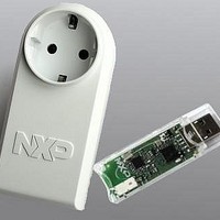
BOARD EVAL EM773 METER EU PLUG
Manufacturer
NXP Semiconductors
Type
Other Power Managementr
Specifications of OM13006,598
Design Resources
Plug Meter Schematics, Gerber Files USB Dongle Schematics, Gerber Files
Main Purpose
Power Management, Energy/Power Meter
Embedded
Yes, MCU, 32-Bit
Utilized Ic / Part
EM773FHN33,551
Interface Type
USB
Maximum Operating Temperature
+ 150 C
Operating Supply Voltage
1.8 V to 3.6 V
Product
Power Management Development Tools
Lead Free Status / RoHS Status
Lead free / RoHS Compliant
Primary Attributes
-
Secondary Attributes
-
Lead Free Status / Rohs Status
Lead free / RoHS Compliant
For Use With/related Products
EM773, OL2381
Other names
568-6681


NXP Semiconductors
20.3 Processor
UM10415
User manual
20.3.1.1 Processor modes
20.3.1.2 Stacks
20.3.1.3 Core registers
20.3.1 Programmers model
System Control Block — The System Control Block (SCB) is the programmers model
interface to the processor. It provides system implementation information and system
control, including configuration, control, and reporting of system exceptions.
System timer — The system timer, SysTick, is a 24-bit count-down timer. Use this as a
Real Time Operating System (RTOS) tick timer or as a simple counter.
This section describes the Cortex-M0 programmers model. In addition to the individual
core register descriptions, it contains information about the processor modes and stacks.
The processor modes are:
Thread mode — Used to execute application software. The processor enters Thread
mode when it comes out of reset.
Handler mode — Used to handle exceptions. The processor returns to Thread mode
when it has finished all exception processing.
The processor uses a full descending stack. This means the stack pointer indicates the
last stacked item on the stack memory. When the processor pushes a new item onto the
stack, it decrements the stack pointer and then writes the item to the new memory
location. The processor implements two stacks, the main stack and the process stack,
with independent copies of the stack pointer, see
In Thread mode, the CONTROL register controls whether the processor uses the main
stack or the process stack, see
always uses the main stack. The options for processor operations are:
Table 216. Summary of processor mode and stack use options
The processor core registers are:
Processor
mode
Thread
Handler
All information provided in this document is subject to legal disclaimers.
Used to
execute
Applications
Exception
handlers
Rev. 1 — 10 September 2010
Chapter 20: Appendix EM773 ARM Cortex-M0 reference
Section
Stack used
Main stack or process stack
See
Main stack
20–20.3.1.3.7. In Handler mode, the processor
Section 20–20.3.1.3.7
Section
20.3.1.3.2.
UM10415
© NXP B.V. 2010. All rights reserved.
227 of 310
Related parts for OM13006,598
Image
Part Number
Description
Manufacturer
Datasheet
Request
R

Part Number:
Description:
NXP Semiconductors designed the LPC2420/2460 microcontroller around a 16-bit/32-bitARM7TDMI-S CPU core with real-time debug interfaces that include both JTAG andembedded trace
Manufacturer:
NXP Semiconductors
Datasheet:

Part Number:
Description:
NXP Semiconductors designed the LPC2458 microcontroller around a 16-bit/32-bitARM7TDMI-S CPU core with real-time debug interfaces that include both JTAG andembedded trace
Manufacturer:
NXP Semiconductors
Datasheet:
Part Number:
Description:
NXP Semiconductors designed the LPC2468 microcontroller around a 16-bit/32-bitARM7TDMI-S CPU core with real-time debug interfaces that include both JTAG andembedded trace
Manufacturer:
NXP Semiconductors
Datasheet:
Part Number:
Description:
NXP Semiconductors designed the LPC2470 microcontroller, powered by theARM7TDMI-S core, to be a highly integrated microcontroller for a wide range ofapplications that require advanced communications and high quality graphic displays
Manufacturer:
NXP Semiconductors
Datasheet:
Part Number:
Description:
NXP Semiconductors designed the LPC2478 microcontroller, powered by theARM7TDMI-S core, to be a highly integrated microcontroller for a wide range ofapplications that require advanced communications and high quality graphic displays
Manufacturer:
NXP Semiconductors
Datasheet:
Part Number:
Description:
The Philips Semiconductors XA (eXtended Architecture) family of 16-bit single-chip microcontrollers is powerful enough to easily handle the requirements of high performance embedded applications, yet inexpensive enough to compete in the market for hi
Manufacturer:
NXP Semiconductors
Datasheet:
Part Number:
Description:
The XA-S3 device is a member of Philips Semiconductors? XA(eXtended Architecture) family of high performance 16-bitsingle-chip microcontrollers
Manufacturer:
NXP Semiconductors
Datasheet:

Part Number:
Description:
The NXP BlueStreak LH75401/LH75411 family consists of two low-cost 16/32-bit System-on-Chip (SoC) devices
Manufacturer:
NXP Semiconductors
Datasheet:
Part Number:
Description:
The NXP LPC3130/3131 combine an 180 MHz ARM926EJ-S CPU core, high-speed USB2
Manufacturer:
NXP Semiconductors
Datasheet:
Part Number:
Description:
The NXP LPC3141 combine a 270 MHz ARM926EJ-S CPU core, High-speed USB 2
Manufacturer:
NXP Semiconductors
Part Number:
Description:
The NXP LPC3143 combine a 270 MHz ARM926EJ-S CPU core, High-speed USB 2
Manufacturer:
NXP Semiconductors

Part Number:
Description:
The NXP LPC3152 combines an 180 MHz ARM926EJ-S CPU core, High-speed USB 2
Manufacturer:
NXP Semiconductors
Part Number:
Description:
The NXP LPC3154 combines an 180 MHz ARM926EJ-S CPU core, High-speed USB 2
Manufacturer:
NXP Semiconductors

Part Number:
Description:
Standard level N-channel enhancement mode Field-Effect Transistor (FET) in a plastic package using NXP High-Performance Automotive (HPA) TrenchMOS technology
Manufacturer:
NXP Semiconductors
Datasheet: