OM13006,598 NXP Semiconductors, OM13006,598 Datasheet - Page 181
OM13006,598
Manufacturer Part Number
OM13006,598
Description
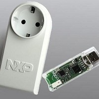
BOARD EVAL EM773 METER EU PLUG
Manufacturer
NXP Semiconductors
Type
Other Power Managementr
Specifications of OM13006,598
Design Resources
Plug Meter Schematics, Gerber Files USB Dongle Schematics, Gerber Files
Main Purpose
Power Management, Energy/Power Meter
Embedded
Yes, MCU, 32-Bit
Utilized Ic / Part
EM773FHN33,551
Interface Type
USB
Maximum Operating Temperature
+ 150 C
Operating Supply Voltage
1.8 V to 3.6 V
Product
Power Management Development Tools
Lead Free Status / RoHS Status
Lead free / RoHS Compliant
Primary Attributes
-
Secondary Attributes
-
Lead Free Status / Rohs Status
Lead free / RoHS Compliant
For Use With/related Products
EM773, OL2381
Other names
568-6681


NXP Semiconductors
UM10415
User manual
14.7.2 Watchdog Timer Constant register (WDTC - 0x4000 4004)
14.7.3 Watchdog Feed register (WDFEED - 0x4000 4008)
14.7.4 Watchdog Timer Value register (WDTV - 0x4000 400C)
Table 170. Watchdog operating modes selection
The WDTC register determines the time-out value. Every time a feed sequence occurs
the WDTC content is reloaded in to the Watchdog timer. It’s a 32-bit register with 8 LSB
set to 1 on reset. Writing values below 0xFF will cause 0x0000 00FF to be loaded to the
WDTC. Thus the minimum time-out interval is T
Table 171. Watchdog Constant register (WDTC - address 0x4000 4004) bit description
Writing 0xAA followed by 0x55 to this register will reload the Watchdog timer with the
WDTC value. This operation will also start the Watchdog if it is enabled via the WDMOD
register. Setting the WDEN bit in the WDMOD register is not sufficient to enable the
Watchdog. A valid feed sequence must be completed after setting WDEN before the
Watchdog is capable of generating a reset. Until then, the Watchdog will ignore feed
errors. After writing 0xAA to WDFEED, access to any Watchdog register other than writing
0x55 to WDFEED causes an immediate reset/interrupt when the Watchdog is enabled.
The reset will be generated during the second PCLK following an incorrect access to a
Watchdog register during a feed sequence.
Interrupts should be disabled during the feed sequence. An abort condition will occur if an
interrupt happens during the feed sequence.
Table 172. Watchdog Feed register (WDFEED - address 0x4000 4008) bit description
The WDTV register is used to read the current value of Watchdog timer.
WDEN
0
1
1
Bit
23:0
31:24
Bit
7:0
31:8
Symbol
Count
-
Symbol
Feed
-
WDRESET
X (0 or 1)
0
1
All information provided in this document is subject to legal disclaimers.
Description
Watchdog time-out interval.
reserved
Description
Feed value should be 0xAA followed by 0x55.
reserved
Rev. 1 — 10 September 2010
Mode of Operation
Debug/Operate without the Watchdog running.
Watchdog interrupt mode: debug with the Watchdog interrupt but no
WDRESET enabled.
When this mode is selected, a watchdog counter underflow will set the
WDINT flag and the Watchdog interrupt request will be generated.
Watchdog reset mode: operate with the Watchdog interrupt and
WDRESET enabled.
When this mode is selected, a watchdog counter underflow will reset
the microcontroller. Although the Watchdog interrupt is also enabled in
this case (WDEN = 1) it will not be recognized since the watchdog
reset will clear the WDINT flag.
Chapter 14: EM773 WatchDog Timer (WDT)
WDCLK
× 256 × 4.
UM10415
© NXP B.V. 2010. All rights reserved.
Reset Value
0x0000 00FF
-
Reset Value
NA
-
181 of 310
Related parts for OM13006,598
Image
Part Number
Description
Manufacturer
Datasheet
Request
R

Part Number:
Description:
NXP Semiconductors designed the LPC2420/2460 microcontroller around a 16-bit/32-bitARM7TDMI-S CPU core with real-time debug interfaces that include both JTAG andembedded trace
Manufacturer:
NXP Semiconductors
Datasheet:

Part Number:
Description:
NXP Semiconductors designed the LPC2458 microcontroller around a 16-bit/32-bitARM7TDMI-S CPU core with real-time debug interfaces that include both JTAG andembedded trace
Manufacturer:
NXP Semiconductors
Datasheet:
Part Number:
Description:
NXP Semiconductors designed the LPC2468 microcontroller around a 16-bit/32-bitARM7TDMI-S CPU core with real-time debug interfaces that include both JTAG andembedded trace
Manufacturer:
NXP Semiconductors
Datasheet:
Part Number:
Description:
NXP Semiconductors designed the LPC2470 microcontroller, powered by theARM7TDMI-S core, to be a highly integrated microcontroller for a wide range ofapplications that require advanced communications and high quality graphic displays
Manufacturer:
NXP Semiconductors
Datasheet:
Part Number:
Description:
NXP Semiconductors designed the LPC2478 microcontroller, powered by theARM7TDMI-S core, to be a highly integrated microcontroller for a wide range ofapplications that require advanced communications and high quality graphic displays
Manufacturer:
NXP Semiconductors
Datasheet:
Part Number:
Description:
The Philips Semiconductors XA (eXtended Architecture) family of 16-bit single-chip microcontrollers is powerful enough to easily handle the requirements of high performance embedded applications, yet inexpensive enough to compete in the market for hi
Manufacturer:
NXP Semiconductors
Datasheet:
Part Number:
Description:
The XA-S3 device is a member of Philips Semiconductors? XA(eXtended Architecture) family of high performance 16-bitsingle-chip microcontrollers
Manufacturer:
NXP Semiconductors
Datasheet:

Part Number:
Description:
The NXP BlueStreak LH75401/LH75411 family consists of two low-cost 16/32-bit System-on-Chip (SoC) devices
Manufacturer:
NXP Semiconductors
Datasheet:
Part Number:
Description:
The NXP LPC3130/3131 combine an 180 MHz ARM926EJ-S CPU core, high-speed USB2
Manufacturer:
NXP Semiconductors
Datasheet:
Part Number:
Description:
The NXP LPC3141 combine a 270 MHz ARM926EJ-S CPU core, High-speed USB 2
Manufacturer:
NXP Semiconductors
Part Number:
Description:
The NXP LPC3143 combine a 270 MHz ARM926EJ-S CPU core, High-speed USB 2
Manufacturer:
NXP Semiconductors

Part Number:
Description:
The NXP LPC3152 combines an 180 MHz ARM926EJ-S CPU core, High-speed USB 2
Manufacturer:
NXP Semiconductors
Part Number:
Description:
The NXP LPC3154 combines an 180 MHz ARM926EJ-S CPU core, High-speed USB 2
Manufacturer:
NXP Semiconductors

Part Number:
Description:
Standard level N-channel enhancement mode Field-Effect Transistor (FET) in a plastic package using NXP High-Performance Automotive (HPA) TrenchMOS technology
Manufacturer:
NXP Semiconductors
Datasheet: