OM13006,598 NXP Semiconductors, OM13006,598 Datasheet - Page 133
OM13006,598
Manufacturer Part Number
OM13006,598
Description
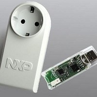
BOARD EVAL EM773 METER EU PLUG
Manufacturer
NXP Semiconductors
Type
Other Power Managementr
Specifications of OM13006,598
Design Resources
Plug Meter Schematics, Gerber Files USB Dongle Schematics, Gerber Files
Main Purpose
Power Management, Energy/Power Meter
Embedded
Yes, MCU, 32-Bit
Utilized Ic / Part
EM773FHN33,551
Interface Type
USB
Maximum Operating Temperature
+ 150 C
Operating Supply Voltage
1.8 V to 3.6 V
Product
Power Management Development Tools
Lead Free Status / RoHS Status
Lead free / RoHS Compliant
Primary Attributes
-
Secondary Attributes
-
Lead Free Status / Rohs Status
Lead free / RoHS Compliant
For Use With/related Products
EM773, OL2381
Other names
568-6681


NXP Semiconductors
UM10415
User manual
10.12.5.1 State: 0x00
10.12.5.2 Master States
10.12.5.3 State: 0x08
10.12.3 Start Master Receive function
10.12.4 I
10.12.5 Non mode specific states
Begin a Master Receive operation by setting up the buffer, pointer, and data count, then
initiating a START.
Determine the I
Bus Error. Enter not addressed Slave mode and release bus.
State 08 and State 10 are for both Master Transmit and Master Receive modes. The R/W
bit decides whether the next state is within Master Transmit mode or Master Receive
mode.
A START condition has been transmitted. The Slave Address + R/W bit will be
transmitted, an ACK bit will be received.
2
2. Set up the Slave Address to which data will be transmitted, and add the Write bit.
3. Write 0x20 to I2CONSET to set the STA bit.
4. Set up data to be transmitted in Master Transmit buffer.
5. Initialize the Master data counter to match the length of the message being sent.
6. Exit
1. Initialize Master data counter.
2. Set up the Slave Address to which data will be transmitted, and add the Read bit.
3. Write 0x20 to I2CONSET to set the STA bit.
4. Set up the Master Receive buffer.
5. Initialize the Master data counter to match the length of the message to be received.
6. Exit
1. Read the I
2. Use the status value to branch to one of 26 possible state routines.
1. Write 0x14 to I2CONSET to set the STO and AA bits.
2. Write 0x08 to I2CONCLR to clear the SI flag.
3. Exit
1. Write Slave Address with R/W bit to I2DAT.
2. Write 0x04 to I2CONSET to set the AA bit.
3. Write 0x08 to I2CONCLR to clear the SI flag.
4. Set up Master Transmit mode data buffer.
C interrupt routine
2
2
C status from I2STA.
All information provided in this document is subject to legal disclaimers.
C state and which state routine will be used to handle it.
Rev. 1 — 10 September 2010
Chapter 10: EM773 I2C-bus interface
UM10415
© NXP B.V. 2010. All rights reserved.
133 of 310
Related parts for OM13006,598
Image
Part Number
Description
Manufacturer
Datasheet
Request
R

Part Number:
Description:
NXP Semiconductors designed the LPC2420/2460 microcontroller around a 16-bit/32-bitARM7TDMI-S CPU core with real-time debug interfaces that include both JTAG andembedded trace
Manufacturer:
NXP Semiconductors
Datasheet:

Part Number:
Description:
NXP Semiconductors designed the LPC2458 microcontroller around a 16-bit/32-bitARM7TDMI-S CPU core with real-time debug interfaces that include both JTAG andembedded trace
Manufacturer:
NXP Semiconductors
Datasheet:
Part Number:
Description:
NXP Semiconductors designed the LPC2468 microcontroller around a 16-bit/32-bitARM7TDMI-S CPU core with real-time debug interfaces that include both JTAG andembedded trace
Manufacturer:
NXP Semiconductors
Datasheet:
Part Number:
Description:
NXP Semiconductors designed the LPC2470 microcontroller, powered by theARM7TDMI-S core, to be a highly integrated microcontroller for a wide range ofapplications that require advanced communications and high quality graphic displays
Manufacturer:
NXP Semiconductors
Datasheet:
Part Number:
Description:
NXP Semiconductors designed the LPC2478 microcontroller, powered by theARM7TDMI-S core, to be a highly integrated microcontroller for a wide range ofapplications that require advanced communications and high quality graphic displays
Manufacturer:
NXP Semiconductors
Datasheet:
Part Number:
Description:
The Philips Semiconductors XA (eXtended Architecture) family of 16-bit single-chip microcontrollers is powerful enough to easily handle the requirements of high performance embedded applications, yet inexpensive enough to compete in the market for hi
Manufacturer:
NXP Semiconductors
Datasheet:
Part Number:
Description:
The XA-S3 device is a member of Philips Semiconductors? XA(eXtended Architecture) family of high performance 16-bitsingle-chip microcontrollers
Manufacturer:
NXP Semiconductors
Datasheet:

Part Number:
Description:
The NXP BlueStreak LH75401/LH75411 family consists of two low-cost 16/32-bit System-on-Chip (SoC) devices
Manufacturer:
NXP Semiconductors
Datasheet:
Part Number:
Description:
The NXP LPC3130/3131 combine an 180 MHz ARM926EJ-S CPU core, high-speed USB2
Manufacturer:
NXP Semiconductors
Datasheet:
Part Number:
Description:
The NXP LPC3141 combine a 270 MHz ARM926EJ-S CPU core, High-speed USB 2
Manufacturer:
NXP Semiconductors
Part Number:
Description:
The NXP LPC3143 combine a 270 MHz ARM926EJ-S CPU core, High-speed USB 2
Manufacturer:
NXP Semiconductors

Part Number:
Description:
The NXP LPC3152 combines an 180 MHz ARM926EJ-S CPU core, High-speed USB 2
Manufacturer:
NXP Semiconductors
Part Number:
Description:
The NXP LPC3154 combines an 180 MHz ARM926EJ-S CPU core, High-speed USB 2
Manufacturer:
NXP Semiconductors

Part Number:
Description:
Standard level N-channel enhancement mode Field-Effect Transistor (FET) in a plastic package using NXP High-Performance Automotive (HPA) TrenchMOS technology
Manufacturer:
NXP Semiconductors
Datasheet: