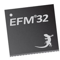
EFM32TG210F32 Energy Micro, EFM32TG210F32 Datasheet - Page 521

EFM32TG210F32
Manufacturer Part Number
EFM32TG210F32
Description
MCU 32BIT 32KB FLASH 32-QFN
Manufacturer
Energy Micro
Series
Tiny Geckor
Specifications of EFM32TG210F32
Core Processor
ARM® Cortex-M3™
Core Size
32-Bit
Speed
32MHz
Connectivity
EBI/EMI, I²C, IrDA, SmartCard, SPI, UART/USART
Peripherals
Brown-out Detect/Reset, DMA, POR, PWM, WDT
Number Of I /o
24
Program Memory Size
32KB (32K x 8)
Program Memory Type
FLASH
Ram Size
4K x 8
Voltage - Supply (vcc/vdd)
1.8 V ~ 3.8 V
Data Converters
A/D 4x12b, D/A 1x12b
Oscillator Type
External
Operating Temperature
-40°C ~ 85°C
Package / Case
32-VQFN Exposed Pad
Processor Series
EFM32
Core
ARM Cortex-M3
Data Bus Width
32 bit
Data Ram Size
32 KB
Interface Type
UART, I2C, SPI
Maximum Clock Frequency
32 MHz
Number Of Programmable I/os
17
Number Of Timers
1
Operating Supply Voltage
1.8 V to 3.8 V
Maximum Operating Temperature
+ 85 C
Mounting Style
SMD/SMT
Processor To Be Evaluated
EFM32TG210
Lead Free Status / RoHS Status
Lead free / RoHS Compliant
Eeprom Size
-
Lead Free Status / Rohs Status
Details
- Current page: 521 of 522
- Download datasheet (9Mb)
2010-12-21 - d0034_Rev0.90
List of Equations
5.1. Memory SRAM Area Set/Clear Bit ............................................................................................................ 14
5.2. Memory Peripheral Area Bit Modification ................................................................................................... 15
5.3. Memory Wait Cycles with Clock Equal or Faster than the HFCORECLK .......................................................... 18
5.4. Memory Wait Cycles with Clock Slower than the CPU .................................................................................. 18
12.1. WDOG Timeout Equation .................................................................................................................... 126
14.1. I
14.2. I
14.3. I
15.1. USART Baud Rate ............................................................................................................................. 177
15.2. USART Desired Baud Rate ................................................................................................................. 177
15.3. USART Synchronous Mode Bit Rate ..................................................................................................... 189
15.4. USART Synchronous Mode Clock Division Factor .................................................................................... 189
16.1. LEUART Baud Rate Equation .............................................................................................................. 221
16.2. LEUART CLKDIV Equation .................................................................................................................. 221
16.3. LEUART Optimal Sampling Point .......................................................................................................... 224
16.4. LEUART Actual Sampling Point ............................................................................................................ 225
17.1. TIMER Rotational Position Equation ...................................................................................................... 250
17.2. TIMER Up-count Frequency Generation Equation .................................................................................... 254
17.3. TIMER Up-count PWM Resolution Equation ............................................................................................ 254
17.4. TIMER Up-count PWM Frequency Equation ............................................................................................ 255
17.5. TIMER Up-count Duty Cycle Equation ................................................................................................... 255
17.6. TIMER 2x PWM Resolution Equation .................................................................................................... 255
17.7. TIMER 2x Mode PWM Frequency Equation( Up-count) ............................................................................. 255
17.8. TIMER 2x Mode Duty Cycle Equation .................................................................................................... 255
17.9. TIMER Up/Down-count PWM Resolution Equation ................................................................................... 256
17.10. TIMER Up/Down-count PWM Frequency Equation .................................................................................. 256
17.11. TIMER Up/Down-count Duty Cycle Equation ......................................................................................... 256
17.12. TIMER 2x PWM Resolution Equation ................................................................................................... 256
17.13. TIMER 2x Mode PWM Frequency Equation( Up/Down-count) ................................................................... 257
17.14. TIMER 2x Mode Duty Cycle Equation .................................................................................................. 257
18.1. RTC Frequency Equation .................................................................................................................... 272
19.1. LETIMER Clock Frequency .................................................................................................................. 286
20.1. Absolute position with hysteresis and even TOP value .............................................................................. 305
20.2. Absolute position with hysteresis and odd TOP value ............................................................................... 305
21.1. Scan frequency ................................................................................................................................. 320
22.1. V
23.1. VCMP V
24.1. ADC Total Conversion Time (in ADC_CLK cycles) Per Output .................................................................... 384
24.2. ADC Temperature Measurement .......................................................................................................... 386
25.1. DAC Clock Prescaling ........................................................................................................................ 407
25.2. DAC Single Ended Output Voltage ........................................................................................................ 408
25.3. DAC Differential Output Voltage ........................................................................................................... 408
25.4. DAC Sine Generation ......................................................................................................................... 409
29.1. LCD Framerate Calculation .................................................................................................................. 489
29.2. LCD Event Frequency Equation ............................................................................................................ 490
2
2
2
C Pull-up Resistor Equation ............................................................................................................... 141
C Maximum Transmission Rate .......................................................................................................... 145
C High and Low Cycles Equations ...................................................................................................... 145
DD
Scaled ....................................................................................................................................... 366
DD
Trigger Level .................................................................................................................... 376
...the world's most energy friendly microcontrollers
521
www.energymicro.com
Related parts for EFM32TG210F32
Image
Part Number
Description
Manufacturer
Datasheet
Request
R

Part Number:
Description:
KIT STARTER EFM32 GECKO
Manufacturer:
Energy Micro
Datasheet:

Part Number:
Description:
KIT DEV EFM32 GECKO LCD SUPPORT
Manufacturer:
Energy Micro
Datasheet:

Part Number:
Description:
BOARD PROTOTYPING FOR EFM32
Manufacturer:
Energy Micro
Datasheet:

Part Number:
Description:
KIT DEVELOPMENT EFM32 GECKO
Manufacturer:
Energy Micro
Datasheet:

Part Number:
Description:
MCU, MPU & DSP Development Tools TG840 Sample Kit
Manufacturer:
Energy Micro
Datasheet:

Part Number:
Description:
MCU, MPU & DSP Development Tools TG Starter Kit
Manufacturer:
Energy Micro
Datasheet:

Part Number:
Description:
MCU, MPU & DSP Development Tools TG108 Sample Kit
Manufacturer:
Energy Micro

Part Number:
Description:
MCU, MPU & DSP Development Tools TG210 Sample Kit
Manufacturer:
Energy Micro
Datasheet:

Part Number:
Description:
MCU, MPU & DSP Development Tools TG822 Sample Kit
Manufacturer:
Energy Micro
Datasheet:

Part Number:
Description:
MCU, MPU & DSP Development Tools TG230 Sample Kit
Manufacturer:
Energy Micro

Part Number:
Description:
SAMPLE KIT (SMALL BOX - CONTAINING 2 DEVICES)
Manufacturer:
Energy Micro

Part Number:
Description:
SAMPLE KIT (SMALL BOX - CONTAINING 2 DEVICES)
Manufacturer:
Energy Micro


