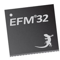
EFM32TG210F32 Energy Micro, EFM32TG210F32 Datasheet - Page 473

EFM32TG210F32
Manufacturer Part Number
EFM32TG210F32
Description
MCU 32BIT 32KB FLASH 32-QFN
Manufacturer
Energy Micro
Series
Tiny Geckor
Specifications of EFM32TG210F32
Core Processor
ARM® Cortex-M3™
Core Size
32-Bit
Speed
32MHz
Connectivity
EBI/EMI, I²C, IrDA, SmartCard, SPI, UART/USART
Peripherals
Brown-out Detect/Reset, DMA, POR, PWM, WDT
Number Of I /o
24
Program Memory Size
32KB (32K x 8)
Program Memory Type
FLASH
Ram Size
4K x 8
Voltage - Supply (vcc/vdd)
1.8 V ~ 3.8 V
Data Converters
A/D 4x12b, D/A 1x12b
Oscillator Type
External
Operating Temperature
-40°C ~ 85°C
Package / Case
32-VQFN Exposed Pad
Processor Series
EFM32
Core
ARM Cortex-M3
Data Bus Width
32 bit
Data Ram Size
32 KB
Interface Type
UART, I2C, SPI
Maximum Clock Frequency
32 MHz
Number Of Programmable I/os
17
Number Of Timers
1
Operating Supply Voltage
1.8 V to 3.8 V
Maximum Operating Temperature
+ 85 C
Mounting Style
SMD/SMT
Processor To Be Evaluated
EFM32TG210
Lead Free Status / RoHS Status
Lead free / RoHS Compliant
Eeprom Size
-
Lead Free Status / Rohs Status
Details
- Current page: 473 of 522
- Download datasheet (9Mb)
29.3 Functional Description
29.3.1 LCD Driver Enable
2010-12-21 - d0034_Rev0.90
• LCD frame interrupt
• Direct segment control
An overview of the LCD module is shown in Figure 29.1 (p. 473) . In its simplest form, an LCD driver
would apply a voltage above a certain threshold voltage in order to darken a segment and a voltage below
threshold to make a segment clear. However, the LCD display segment will degrade if the applied voltage
has a DC-component. To avoid this, the applied waveforms are arranged such that the differential voltage
seen by each segment has an average value of zero, and such that the RMS voltage (or differential sum
of the two waveforms for fast response LCDs) is below the segment threshold voltage if the segment
shall be transparent, and above the segment threshold voltage when the segment shall be dark.
The waveforms are multiplexed up to eight (1-8) different common lines and 20-24 segment lines to
support up to 160 different LCD segments. The common lines and segment lines can be enabled or
disabled individually to prevent the LCD driver from occupying more I/O resources than required.
Figure 29.1. LCD Block Diagram
For simplicity, only one segment pin and one common terminal is shown in the figure.
Setting the EN bit in LCD_CTRL enables the LCD driver. The MUX bitfield in LCD_DISPCTRL
determines which COM lines are driven by the LCD driver. By default, LCD_COM0 is driven whenever
the LCD driver is enabled.
The LCD_SEGEN register determines which segment lines are enabled. Segment lines can be enabled
in groups of 4 and disabled in groups of 4 or individually disabled. To enable output on segment lines
0-7 for instance, the two lowest segment groups, set the two lowest bits in LCD_SEGEN. Disabling
individual segment lines can be done by disabling the pin in GPIO.
Each LCD segment pin can also be individually disabled by configuring the pin as input in the GPIO.
LFACLK
LCD
LCD control and
LCD anim ation
LCD segm ent
data register
registers
status
Display data
Mux and fram erate setting
Special
effects
Contrast and bias setting
sequence
generator
V
INT
LCD
...the world's most energy friendly microcontrollers
generator
473
voltage
LCD
V
BOOST
V
EXT
VLCDSEL
V
V
V
V
V
V
V
V
V
V
LC4
LC3
LC2
LC1
LC0
LC4
LC3
LC2
LC1
LC0
COM out
SEG out
Disable
Disable
www.energymicro.com
4x SEG/COM
LCD_COMx
LCD_SEGx
LCD_BCAP_N
LCD_BCAP_P
20x SEG
LCD_BEXT
4x
Related parts for EFM32TG210F32
Image
Part Number
Description
Manufacturer
Datasheet
Request
R

Part Number:
Description:
KIT STARTER EFM32 GECKO
Manufacturer:
Energy Micro
Datasheet:

Part Number:
Description:
KIT DEV EFM32 GECKO LCD SUPPORT
Manufacturer:
Energy Micro
Datasheet:

Part Number:
Description:
BOARD PROTOTYPING FOR EFM32
Manufacturer:
Energy Micro
Datasheet:

Part Number:
Description:
KIT DEVELOPMENT EFM32 GECKO
Manufacturer:
Energy Micro
Datasheet:

Part Number:
Description:
MCU, MPU & DSP Development Tools TG840 Sample Kit
Manufacturer:
Energy Micro
Datasheet:

Part Number:
Description:
MCU, MPU & DSP Development Tools TG Starter Kit
Manufacturer:
Energy Micro
Datasheet:

Part Number:
Description:
MCU, MPU & DSP Development Tools TG108 Sample Kit
Manufacturer:
Energy Micro

Part Number:
Description:
MCU, MPU & DSP Development Tools TG210 Sample Kit
Manufacturer:
Energy Micro
Datasheet:

Part Number:
Description:
MCU, MPU & DSP Development Tools TG822 Sample Kit
Manufacturer:
Energy Micro
Datasheet:

Part Number:
Description:
MCU, MPU & DSP Development Tools TG230 Sample Kit
Manufacturer:
Energy Micro

Part Number:
Description:
SAMPLE KIT (SMALL BOX - CONTAINING 2 DEVICES)
Manufacturer:
Energy Micro

Part Number:
Description:
SAMPLE KIT (SMALL BOX - CONTAINING 2 DEVICES)
Manufacturer:
Energy Micro


