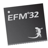
EFM32TG210F32 Energy Micro, EFM32TG210F32 Datasheet - Page 176

EFM32TG210F32
Manufacturer Part Number
EFM32TG210F32
Description
MCU 32BIT 32KB FLASH 32-QFN
Manufacturer
Energy Micro
Series
Tiny Geckor
Specifications of EFM32TG210F32
Core Processor
ARM® Cortex-M3™
Core Size
32-Bit
Speed
32MHz
Connectivity
EBI/EMI, I²C, IrDA, SmartCard, SPI, UART/USART
Peripherals
Brown-out Detect/Reset, DMA, POR, PWM, WDT
Number Of I /o
24
Program Memory Size
32KB (32K x 8)
Program Memory Type
FLASH
Ram Size
4K x 8
Voltage - Supply (vcc/vdd)
1.8 V ~ 3.8 V
Data Converters
A/D 4x12b, D/A 1x12b
Oscillator Type
External
Operating Temperature
-40°C ~ 85°C
Package / Case
32-VQFN Exposed Pad
Processor Series
EFM32
Core
ARM Cortex-M3
Data Bus Width
32 bit
Data Ram Size
32 KB
Interface Type
UART, I2C, SPI
Maximum Clock Frequency
32 MHz
Number Of Programmable I/os
17
Number Of Timers
1
Operating Supply Voltage
1.8 V to 3.8 V
Maximum Operating Temperature
+ 85 C
Mounting Style
SMD/SMT
Processor To Be Evaluated
EFM32TG210
Lead Free Status / RoHS Status
Lead free / RoHS Compliant
Eeprom Size
-
Lead Free Status / Rohs Status
Details
- Current page: 176 of 522
- Download datasheet (9Mb)
15.3.2.1.1 Parity bit Calculation and Handling
2010-12-21 - d0034_Rev0.90
Table 15.3. USART Data Bits
Table 15.4. USART Stop Bits
The order in which the data bits are transmitted and received is defined by MSBF in USARTn_CTRL.
When MSBF is cleared, data in a frame is sent and received with the least significant bit first. When it
is set, the most significant bit comes first.
The frame format used by the transmitter can be inverted by setting TXINV in USARTn_CTRL, and the
format expected by the receiver can be inverted by setting RXINV in USARTn_CTRL. These bits affect
the entire frame, not only the data bits. An inverted frame has a low idle state, a high start-bit, inverted
data and parity bits, and low stop-bits.
When parity bits are enabled, hardware automatically calculates and inserts any parity bits into outgoing
frames, and verifies the received parity bits in incoming frames. This is true for both asynchronous and
synchronous modes, even though it is mostly used in asynchronous communication. The possible parity
modes are defined in Table 15.5 (p. 177) . When even parity is chosen, a parity bit is inserted to make
the number of high bits (data + parity) even. If odd parity is chosen, the parity bit makes the total number
of high bits odd.
DATA BITS [3:0]
0001
0010
0011
0100
0101
0110
0111
1000
1001
1010
1011
1100
1101
STOP BITS [1:0]
00
01
10
11
...the world's most energy friendly microcontrollers
176
Number of Data bits
4
5
6
7
8 (Default)
9
10
11
12
13
14
15
16
Number of Stop bits
0.5
1 (Default)
1.5
2
www.energymicro.com
Related parts for EFM32TG210F32
Image
Part Number
Description
Manufacturer
Datasheet
Request
R

Part Number:
Description:
KIT STARTER EFM32 GECKO
Manufacturer:
Energy Micro
Datasheet:

Part Number:
Description:
KIT DEV EFM32 GECKO LCD SUPPORT
Manufacturer:
Energy Micro
Datasheet:

Part Number:
Description:
BOARD PROTOTYPING FOR EFM32
Manufacturer:
Energy Micro
Datasheet:

Part Number:
Description:
KIT DEVELOPMENT EFM32 GECKO
Manufacturer:
Energy Micro
Datasheet:

Part Number:
Description:
MCU, MPU & DSP Development Tools TG840 Sample Kit
Manufacturer:
Energy Micro
Datasheet:

Part Number:
Description:
MCU, MPU & DSP Development Tools TG Starter Kit
Manufacturer:
Energy Micro
Datasheet:

Part Number:
Description:
MCU, MPU & DSP Development Tools TG108 Sample Kit
Manufacturer:
Energy Micro

Part Number:
Description:
MCU, MPU & DSP Development Tools TG210 Sample Kit
Manufacturer:
Energy Micro
Datasheet:

Part Number:
Description:
MCU, MPU & DSP Development Tools TG822 Sample Kit
Manufacturer:
Energy Micro
Datasheet:

Part Number:
Description:
MCU, MPU & DSP Development Tools TG230 Sample Kit
Manufacturer:
Energy Micro

Part Number:
Description:
SAMPLE KIT (SMALL BOX - CONTAINING 2 DEVICES)
Manufacturer:
Energy Micro

Part Number:
Description:
SAMPLE KIT (SMALL BOX - CONTAINING 2 DEVICES)
Manufacturer:
Energy Micro


