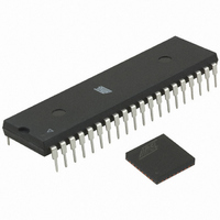
ATMEGA64RZAV-10PU Atmel, ATMEGA64RZAV-10PU Datasheet - Page 371

ATMEGA64RZAV-10PU
Manufacturer Part Number
ATMEGA64RZAV-10PU
Description
MCU ATMEGA644/AT86RF230 40-DIP
Manufacturer
Atmel
Series
ATMEGAr
Datasheets
1.ATMEGA644-20MU.pdf
(23 pages)
2.ATMEGA644-20MU.pdf
(376 pages)
3.AT86RF230-ZU.pdf
(98 pages)
Specifications of ATMEGA64RZAV-10PU
Frequency
2.4GHz
Modulation Or Protocol
802.15.4 Zigbee
Power - Output
3dBm
Sensitivity
-101dBm
Voltage - Supply
1.8 V ~ 3.6 V
Data Interface
PCB, Surface Mount
Memory Size
64kB Flash, 2kB EEPROM, 4kB RAM
Antenna Connector
PCB, Surface Mount
Package / Case
40-DIP (0.600", 15.24mm)
Wireless Frequency
2.4 GHz
Interface Type
JTAG, SPI
Output Power
3 dBm
For Use With
ATSTK600-TQFP32 - STK600 SOCKET/ADAPTER 32-TQFPATAVRISP2 - PROGRAMMER AVR IN SYSTEMATSTK500 - PROGRAMMER AVR STARTER KIT
Lead Free Status / RoHS Status
Lead free / RoHS Compliant
Operating Temperature
-
Applications
-
Data Rate - Maximum
-
Current - Transmitting
-
Current - Receiving
-
Lead Free Status / Rohs Status
Lead free / RoHS Compliant
For Use With/related Products
ATmega64
- Current page: 371 of 376
- Download datasheet (8Mb)
2593N–AVR–07/10
15 8-bit Timer/Counter2 with PWM and Asynchronous Operation ...... 134
16 SPI – Serial Peripheral Interface ......................................................... 155
17 USART ................................................................................................... 164
18 USART in SPI Mode ............................................................................. 191
14.3Timer/Counter Clock Sources .............................................................................111
14.4Counter Unit ........................................................................................................112
14.5Input Capture Unit ...............................................................................................113
14.6Output Compare Units .........................................................................................115
14.7Compare Match Output Unit ................................................................................117
14.8Modes of Operation .............................................................................................118
14.9Timer/Counter Timing Diagrams .........................................................................125
14.1016-bit Timer/Counter Register Description ........................................................127
15.1Overview .............................................................................................................134
15.2Timer/Counter Clock Sources .............................................................................135
15.3Counter Unit ........................................................................................................135
15.4Output Compare Unit ..........................................................................................136
15.5Compare Match Output Unit ................................................................................138
15.6Modes of Operation .............................................................................................139
15.7Timer/Counter Timing Diagrams .........................................................................143
15.88-bit Timer/Counter Register Description ............................................................145
15.9Asynchronous operation of the Timer/Counter ....................................................150
15.10Timer/Counter Prescaler ...................................................................................154
16.1SS Pin Functionality ............................................................................................160
16.2Data Modes .........................................................................................................162
17.1USART0 ..............................................................................................................164
17.2Overview .............................................................................................................164
17.3Clock Generation .................................................................................................165
17.4Frame Formats ....................................................................................................168
17.5USART Initialization ............................................................................................169
17.6Data Transmission – The USART Transmitter ....................................................170
17.7Data Reception – The USART Receiver .............................................................173
17.8Asynchronous Data Reception ............................................................................177
17.9Multi-processor Communication Mode ................................................................180
17.10USART Register Description .............................................................................181
17.11Examples of Baud Rate Setting ........................................................................187
ATmega644
iii
Related parts for ATMEGA64RZAV-10PU
Image
Part Number
Description
Manufacturer
Datasheet
Request
R

Part Number:
Description:
DEV KIT FOR AVR/AVR32
Manufacturer:
Atmel
Datasheet:

Part Number:
Description:
INTERVAL AND WIPE/WASH WIPER CONTROL IC WITH DELAY
Manufacturer:
ATMEL Corporation
Datasheet:

Part Number:
Description:
Low-Voltage Voice-Switched IC for Hands-Free Operation
Manufacturer:
ATMEL Corporation
Datasheet:

Part Number:
Description:
MONOLITHIC INTEGRATED FEATUREPHONE CIRCUIT
Manufacturer:
ATMEL Corporation
Datasheet:

Part Number:
Description:
AM-FM Receiver IC U4255BM-M
Manufacturer:
ATMEL Corporation
Datasheet:

Part Number:
Description:
Monolithic Integrated Feature Phone Circuit
Manufacturer:
ATMEL Corporation
Datasheet:

Part Number:
Description:
Multistandard Video-IF and Quasi Parallel Sound Processing
Manufacturer:
ATMEL Corporation
Datasheet:

Part Number:
Description:
High-performance EE PLD
Manufacturer:
ATMEL Corporation
Datasheet:

Part Number:
Description:
8-bit Flash Microcontroller
Manufacturer:
ATMEL Corporation
Datasheet:

Part Number:
Description:
2-Wire Serial EEPROM
Manufacturer:
ATMEL Corporation
Datasheet:


