HD64F2676VFC33 Renesas Electronics America, HD64F2676VFC33 Datasheet - Page 781
HD64F2676VFC33
Manufacturer Part Number
HD64F2676VFC33
Description
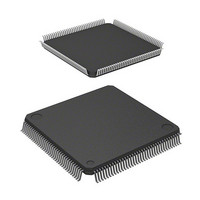
IC H8S MCU FLASH 256K 144-QFP
Manufacturer
Renesas Electronics America
Series
H8® H8S/2600r
Specifications of HD64F2676VFC33
Core Processor
H8S/2600
Core Size
16-Bit
Speed
33MHz
Connectivity
IrDA, SCI
Peripherals
DMA, POR, PWM, WDT
Number Of I /o
103
Program Memory Size
256KB (256K x 8)
Program Memory Type
FLASH
Ram Size
8K x 8
Voltage - Supply (vcc/vdd)
3 V ~ 3.6 V
Data Converters
A/D 12x10b; D/A 4x8b
Oscillator Type
Internal
Operating Temperature
-20°C ~ 75°C
Package / Case
144-QFP
Lead Free Status / RoHS Status
Contains lead / RoHS non-compliant
Eeprom Size
-
Available stocks
Company
Part Number
Manufacturer
Quantity
Price
Company:

Part Number:
HD64F2676VFC33
Manufacturer:
RENESAS
Quantity:
5 530
Company:
Part Number:
HD64F2676VFC33
Manufacturer:
Renesas Electronics America
Quantity:
10 000
Company:
Part Number:
HD64F2676VFC33V
Manufacturer:
RENESAS
Quantity:
5 530
Company:
Part Number:
HD64F2676VFC33V
Manufacturer:
ROHM
Quantity:
750 000
Part Number:
HD64F2676VFC33V
Manufacturer:
RENESAS/瑞萨
Quantity:
20 000


When returning to smart card interface mode from software standby mode:
15.8
When the IrDA function is enabled with bit IrE in IrCR, the SCI_0 TxD0 and RxD0 signals are
subjected to waveform encoding/decoding conforming to IrDA specification version 1.0 (IrTxD
and IrRxD pins). By connecting these pins to an infrared transceiver/receiver, it is possible to
implement infrared transmission/reception conforming to the IrDA specification version 1.0
system.
In the IrDA specification version 1.0 system, communication is started at a transfer rate of 9600
bps, and subsequently the transfer rate can be varied as necessary. As the IrDA interface in this
LSI does not include a function for varying the transfer rate automatically, the transfer rate setting
must be changed by software.
Figure 15.33 shows a block diagram of the IrDA function.
1. Exit the software standby state.
2. Write 1 to the CKE0 bit in SCR and output the clock. Signal generation is started with the
normal duty cycle.
IrDA Operation
[1] [2] [3]
Normal operation
Figure 15.32 Clock Halt and Restart Procedure
[4] [5]
Section 15 Serial Communication Interface (SCI, IrDA)
Software
standby
[6]
Rev. 3.00 Mar 17, 2006 page 729 of 926
[7]
Normal operation
REJ09B0283-0300
Related parts for HD64F2676VFC33
Image
Part Number
Description
Manufacturer
Datasheet
Request
R

Part Number:
Description:
KIT STARTER FOR M16C/29
Manufacturer:
Renesas Electronics America
Datasheet:

Part Number:
Description:
KIT STARTER FOR R8C/2D
Manufacturer:
Renesas Electronics America
Datasheet:

Part Number:
Description:
R0K33062P STARTER KIT
Manufacturer:
Renesas Electronics America
Datasheet:

Part Number:
Description:
KIT STARTER FOR R8C/23 E8A
Manufacturer:
Renesas Electronics America
Datasheet:

Part Number:
Description:
KIT STARTER FOR R8C/25
Manufacturer:
Renesas Electronics America
Datasheet:

Part Number:
Description:
KIT STARTER H8S2456 SHARPE DSPLY
Manufacturer:
Renesas Electronics America
Datasheet:

Part Number:
Description:
KIT STARTER FOR R8C38C
Manufacturer:
Renesas Electronics America
Datasheet:

Part Number:
Description:
KIT STARTER FOR R8C35C
Manufacturer:
Renesas Electronics America
Datasheet:

Part Number:
Description:
KIT STARTER FOR R8CL3AC+LCD APPS
Manufacturer:
Renesas Electronics America
Datasheet:
Part Number:
Description:
KIT STARTER FOR RX610
Manufacturer:
Renesas Electronics America
Datasheet:

Part Number:
Description:
KIT STARTER FOR R32C/118
Manufacturer:
Renesas Electronics America
Datasheet:

Part Number:
Description:
KIT DEV RSK-R8C/26-29
Manufacturer:
Renesas Electronics America
Datasheet:

Part Number:
Description:
KIT STARTER FOR SH7124
Manufacturer:
Renesas Electronics America
Datasheet:

Part Number:
Description:
KIT STARTER FOR H8SX/1622
Manufacturer:
Renesas Electronics America
Datasheet:

Part Number:
Description:
KIT DEV FOR SH7203
Manufacturer:
Renesas Electronics America
Datasheet: