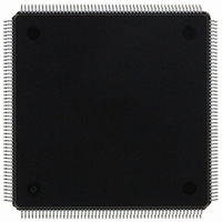
MCF5307AI90B Freescale Semiconductor, MCF5307AI90B Datasheet - Page 80

MCF5307AI90B
Manufacturer Part Number
MCF5307AI90B
Description
IC MPU 32BIT COLDF 90MHZ 208FQFP
Manufacturer
Freescale Semiconductor
Series
MCF530xr
Datasheets
1.MCF5307AI66B.pdf
(484 pages)
2.MCF5307AI66B.pdf
(16 pages)
3.MCF5307AI66B.pdf
(2 pages)
Specifications of MCF5307AI90B
Core Processor
Coldfire V3
Core Size
32-Bit
Speed
90MHz
Connectivity
EBI/EMI, I²C, UART/USART
Peripherals
DMA, POR, WDT
Number Of I /o
16
Program Memory Type
ROMless
Ram Size
4K x 8
Voltage - Supply (vcc/vdd)
3 V ~ 3.6 V
Oscillator Type
External
Operating Temperature
0°C ~ 70°C
Package / Case
208-FQFP
Maximum Clock Frequency
90 MHz
Maximum Operating Temperature
+ 105 C
Mounting Style
SMD/SMT
Minimum Operating Temperature
0 C
Family Name
MCF5xxx
Device Core
ColdFire
Device Core Size
32b
Frequency (max)
90MHz
Instruction Set Architecture
RISC
Supply Voltage 1 (typ)
3.3V
Operating Temp Range
0C to 70C
Operating Temperature Classification
Commercial
Mounting
Surface Mount
Pin Count
208
Package Type
FQFP
Program Memory Size
8KB
Cpu Speed
90MHz
Embedded Interface Type
I2C, UART
Digital Ic Case Style
FQFP
No. Of Pins
208
Supply Voltage Range
3V To 3.6V
Rohs Compliant
Yes
Lead Free Status / RoHS Status
Lead free / RoHS Compliant
Eeprom Size
-
Program Memory Size
-
Data Converters
-
Lead Free Status / Rohs Status
Lead free / RoHS Compliant
Available stocks
Company
Part Number
Manufacturer
Quantity
Price
Company:
Part Number:
MCF5307AI90B
Manufacturer:
FREESCAL
Quantity:
153
Company:
Part Number:
MCF5307AI90B
Manufacturer:
Freescale Semiconductor
Quantity:
10 000
Part Number:
MCF5307AI90B
Manufacturer:
FREESCALE
Quantity:
20 000
- Current page: 80 of 484
- Download datasheet (6Mb)
1
TST
UNLK
WDDATA
Instruction
1
execution by setting CSR[UHE].
By default the HALT instruction is a supervisor-mode instruction; however, it can be configured to allow user-mode
CPUSHL
HALT
MOVE from SR
MOVE to SR
MOVEC
RTE
STOP
WDEBUG
Instruction Timing
Table 2-8 describes supervisor-mode instructions.
2.7 Instruction Timing
The timing data presented in this section assumes the following:
2-40
The HALT instruction can be configured to allow user-mode execution by setting CSR[UHE].
Instruction
• The OEP is loaded with the opword and all required extension words at the
• The OEP experiences no sequence-related pipeline stalls. For the MCF5307, the
1
beginning of each instruction execution. This implies that the OEP spends no time
waiting for the IFP to supply opwords and/or extension words.
most common example of this type of stall involves consecutive store operations,
excluding the MOVEM instruction. For all store operations (except MOVEM),
<ea>y
Ax
<ea>y
Operand Syntax
Table 2-7. User-Mode Instruction Set Summary (Continued)
(An)
none
SR, Dx
Dy,SR
#<data>,SR
Ry,Rc
None
#<data>
<ea-2>y
Operand Syntax Operand Size
Table 2-8. Supervisor-Mode Instruction Set Summary
Freescale Semiconductor, Inc.
For More Information On This Product,
.B,.W,.L
Unsized
.B,.W,.L
Unsized
Unsized
.W
.W
.L
Unsized
.W
.L
Operand Size
Go to: www.freescale.com
MCF5307 User’s Manual
Invalidate instruction cache line
Push and invalidate data cache line
Push data cache line and invalidate (I,D)-cache lines
Enter halted state
SR → Dx
Source → SR
Ry → Rc
Rc
0x002
0x004
0x005
0x006
0x007
0x801
0xC04 RAM base address register 0 (RAMBAR0)
0xC05 RAM base address register 1 (RAMBAR1)
(SP+2) → SR; SP+4 → SP; (SP) → PC; SP + formatfield SP
Immediate data → SR; enter stopped state
<ea-2>y → debug module
Set condition codes
Ax →SP; (SP) → Ax; SP + 4 → SP
<ea>y →DDATA port
Register Definition
Cache control register (CACR)
Access control register 0 (ACR0)
Access control register 1 (ACR1)
Access control register 2 (ACR2)
Access control register 3 (ACR3)
Vector base register (VBR)
Operation
Operation
Related parts for MCF5307AI90B
Image
Part Number
Description
Manufacturer
Datasheet
Request
R
Part Number:
Description:
Manufacturer:
Freescale Semiconductor, Inc
Datasheet:
Part Number:
Description:
Mcf5307 Coldfire Integrated Microprocessor User
Manufacturer:
Freescale Semiconductor, Inc
Datasheet:
Part Number:
Description:
Manufacturer:
Freescale Semiconductor, Inc
Datasheet:
Part Number:
Description:
Manufacturer:
Freescale Semiconductor, Inc
Datasheet:
Part Number:
Description:
Manufacturer:
Freescale Semiconductor, Inc
Datasheet:
Part Number:
Description:
Manufacturer:
Freescale Semiconductor, Inc
Datasheet:
Part Number:
Description:
Manufacturer:
Freescale Semiconductor, Inc
Datasheet:
Part Number:
Description:
Manufacturer:
Freescale Semiconductor, Inc
Datasheet:
Part Number:
Description:
Manufacturer:
Freescale Semiconductor, Inc
Datasheet:
Part Number:
Description:
Manufacturer:
Freescale Semiconductor, Inc
Datasheet:
Part Number:
Description:
Manufacturer:
Freescale Semiconductor, Inc
Datasheet:
Part Number:
Description:
Manufacturer:
Freescale Semiconductor, Inc
Datasheet:
Part Number:
Description:
Manufacturer:
Freescale Semiconductor, Inc
Datasheet:
Part Number:
Description:
Manufacturer:
Freescale Semiconductor, Inc
Datasheet:
Part Number:
Description:
Manufacturer:
Freescale Semiconductor, Inc
Datasheet:


