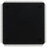
MCF5307AI90B Freescale Semiconductor, MCF5307AI90B Datasheet - Page 70

MCF5307AI90B
Manufacturer Part Number
MCF5307AI90B
Description
IC MPU 32BIT COLDF 90MHZ 208FQFP
Manufacturer
Freescale Semiconductor
Series
MCF530xr
Datasheets
1.MCF5307AI66B.pdf
(484 pages)
2.MCF5307AI66B.pdf
(16 pages)
3.MCF5307AI66B.pdf
(2 pages)
Specifications of MCF5307AI90B
Core Processor
Coldfire V3
Core Size
32-Bit
Speed
90MHz
Connectivity
EBI/EMI, I²C, UART/USART
Peripherals
DMA, POR, WDT
Number Of I /o
16
Program Memory Type
ROMless
Ram Size
4K x 8
Voltage - Supply (vcc/vdd)
3 V ~ 3.6 V
Oscillator Type
External
Operating Temperature
0°C ~ 70°C
Package / Case
208-FQFP
Maximum Clock Frequency
90 MHz
Maximum Operating Temperature
+ 105 C
Mounting Style
SMD/SMT
Minimum Operating Temperature
0 C
Family Name
MCF5xxx
Device Core
ColdFire
Device Core Size
32b
Frequency (max)
90MHz
Instruction Set Architecture
RISC
Supply Voltage 1 (typ)
3.3V
Operating Temp Range
0C to 70C
Operating Temperature Classification
Commercial
Mounting
Surface Mount
Pin Count
208
Package Type
FQFP
Program Memory Size
8KB
Cpu Speed
90MHz
Embedded Interface Type
I2C, UART
Digital Ic Case Style
FQFP
No. Of Pins
208
Supply Voltage Range
3V To 3.6V
Rohs Compliant
Yes
Lead Free Status / RoHS Status
Lead free / RoHS Compliant
Eeprom Size
-
Program Memory Size
-
Data Converters
-
Lead Free Status / Rohs Status
Lead free / RoHS Compliant
Available stocks
Company
Part Number
Manufacturer
Quantity
Price
Company:
Part Number:
MCF5307AI90B
Manufacturer:
FREESCAL
Quantity:
153
Company:
Part Number:
MCF5307AI90B
Manufacturer:
Freescale Semiconductor
Quantity:
10 000
Part Number:
MCF5307AI90B
Manufacturer:
FREESCALE
Quantity:
20 000
- Current page: 70 of 484
- Download datasheet (6Mb)
Programming Model
Table 2-3 describes SR fields.
2.2.2.2 Vector Base Register (VBR)
The VBR holds the base address of the exception vector table in memory. The displacement
of an exception vector is added to the value in this register to access the vector table.
VBR[19–0] are not implemented and are assumed to be zero, forcing the vector table to be
aligned on a 0-modulo-1-Mbyte boundary.
2.2.2.3 Cache Control Register (CACR)
The CACR controls operation of both the instruction and data cache memory. It includes
bits for enabling, freezing, and invalidating cache contents. It also includes bits for defining
the default cache mode and write-protect fields. See Section 4.10.1, “Cache Control
Register (CACR).”
Rc[11–0]
2-30
Reset
15
13
12
10–8
7–0
Field
Bits
R/W R/W
Reset
Field
R/W Written from a BDM serial command or from the CPU using the MOVEC instruction. VBR can be read from
T
S
M
I
CCR
Name
15
T
0
31 30 29 28 27 26 25 24 23 22 21 20 19 18 17 16 15 14 13 12 11 10 9
Exception vector table base address
—
14
R
0
Trace enable. When T is set, the processor performs a trace exception after every instruction.
Supervisor/user state. Indicates whether the processor is in supervisor or user mode
0 User mode
1 Supervisor mode
Master/interrupt state. Cleared by an interrupt exception. It can be set by software during execution
of the RTE or move to SR instructions so the OS can emulate an interrupt stack pointer.
Interrupt priority mask. Defines the current interrupt priority. Interrupt requests are inhibited for all
priority levels less than or equal to the current priority, except the edge-sensitive level-7 request,
which cannot be masked.
Condition code register. See Table 2-1.
the debug module only. The upper 12 bits are returned, the low-order 20 bits are undefined.
R/W
13
S
1
System byte
R/W
12
M
0
Freescale Semiconductor, Inc.
Figure 2-6. Vector Base Register (VBR)
Table 2-3. Status Field Descriptions
For More Information On This Product,
Figure 2-5. Status Register (SR)
—
11
R
0
0000_0000_0000_0000_0000_0000_0000_0000
Go to: www.freescale.com
10
MCF5307 User’s Manual
R/W
111
9
I
8
Description
0x801
R/W
P
0
7
6
Condition code register (CCR)
00
—
R
5
—
R/W
—
X
4
8
R/W
7
—
N
3
6
R/W
5
—
Z
2
4
R/W
3
—
V
1
2
R/W
1
—
C
0
0
Related parts for MCF5307AI90B
Image
Part Number
Description
Manufacturer
Datasheet
Request
R
Part Number:
Description:
Manufacturer:
Freescale Semiconductor, Inc
Datasheet:
Part Number:
Description:
Mcf5307 Coldfire Integrated Microprocessor User
Manufacturer:
Freescale Semiconductor, Inc
Datasheet:
Part Number:
Description:
Manufacturer:
Freescale Semiconductor, Inc
Datasheet:
Part Number:
Description:
Manufacturer:
Freescale Semiconductor, Inc
Datasheet:
Part Number:
Description:
Manufacturer:
Freescale Semiconductor, Inc
Datasheet:
Part Number:
Description:
Manufacturer:
Freescale Semiconductor, Inc
Datasheet:
Part Number:
Description:
Manufacturer:
Freescale Semiconductor, Inc
Datasheet:
Part Number:
Description:
Manufacturer:
Freescale Semiconductor, Inc
Datasheet:
Part Number:
Description:
Manufacturer:
Freescale Semiconductor, Inc
Datasheet:
Part Number:
Description:
Manufacturer:
Freescale Semiconductor, Inc
Datasheet:
Part Number:
Description:
Manufacturer:
Freescale Semiconductor, Inc
Datasheet:
Part Number:
Description:
Manufacturer:
Freescale Semiconductor, Inc
Datasheet:
Part Number:
Description:
Manufacturer:
Freescale Semiconductor, Inc
Datasheet:
Part Number:
Description:
Manufacturer:
Freescale Semiconductor, Inc
Datasheet:
Part Number:
Description:
Manufacturer:
Freescale Semiconductor, Inc
Datasheet:


