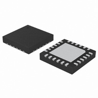
C8051F902-GM Silicon Laboratories Inc, C8051F902-GM Datasheet - Page 199

C8051F902-GM
Manufacturer Part Number
C8051F902-GM
Description
IC MCU 8BIT 8KB FLASH 24QFN
Manufacturer
Silicon Laboratories Inc
Series
C8051F9xxr
Specifications of C8051F902-GM
Program Memory Type
FLASH
Program Memory Size
8KB (8K x 8)
Package / Case
24-QFN
Core Processor
8051
Core Size
8-Bit
Speed
25MHz
Connectivity
SMBus (2-Wire/I²C), SPI, UART/USART
Peripherals
Brown-out Detect/Reset, POR, PWM, Temp Sensor, WDT
Number Of I /o
16
Ram Size
768 x 8
Voltage - Supply (vcc/vdd)
0.9 V ~ 3.6 V
Data Converters
A/D 15x10/12b
Oscillator Type
Internal
Operating Temperature
-40°C ~ 85°C
Processor Series
C8051F9x
Core
8051
Data Ram Size
768 B
Interface Type
UART
Maximum Clock Frequency
25 MHz
Number Of Timers
4
Operating Supply Voltage
0.9 V to 3.6 V
Maximum Operating Temperature
+ 85 C
Mounting Style
SMD/SMT
3rd Party Development Tools
PK51, CA51, A51, ULINK2
Development Tools By Supplier
C8051F912DK
Minimum Operating Temperature
- 40 C
On-chip Adc
12 bit
Package
24QFN EP
Device Core
8051
Family Name
C8051F90x
Maximum Speed
25 MHz
Data Bus Width
8 Bit
Number Of Programmable I/os
16
Lead Free Status / RoHS Status
Lead free / RoHS Compliant
Eeprom Size
-
Lead Free Status / Rohs Status
Lead free / RoHS Compliant
Other names
336-1848-5
- Current page: 199 of 318
- Download datasheet (3Mb)
20.2.6. Missing SmaRTClock Detector
The missing SmaRTClock detector is a one-shot circuit enabled by setting MCLKEN (RTC0CN.6) to 1.
When the SmaRTClock Missing Clock Detector is enabled, OSCFAIL (RTC0CN.5) is set by hardware if
SmaRTClock oscillator remains high or low for more than 100 µs.
A SmaRTClock Missing Clock detector timeout can trigger an interrupt, wake the device from a low power
mode, or reset the device. See Section “12. Interrupt Handler” on page 120, Section “14. Power
Management” on page 143, and Section “18. Reset Sources” on page 171 for more information.
Note: The SmaRTClock Missing Clock Detector should be disabled when making changes to the oscillator settings in
20.2.7. SmaRTClock Oscillator Crystal Valid Detector
The SmaRTClock oscillator crystal valid detector is an oscillation amplitude detector circuit used during
crystal startup to determine when oscillation has started and is nearly stable. The output of this detector
can be read from the CLKVLD bit (RTX0XCN.4).
Notes:
•
•
20.3. SmaRTClock Timer and Alarm Function
The SmaRTClock timer is a 32-bit counter that, when running (RTC0TR = 1), is incremented every
SmaRTClock oscillator cycle. The timer has an alarm function that can be set to generate an interrupt,
wake the device from a low power mode, or reset the device at a specific time. See Section “12. Interrupt
Handler” on page 120, Section “14. Power Management” on page 143, and Section “18. Reset Sources”
on page 171 for more information.
The SmaRTClock timer includes an Auto Reset feature, which automatically resets the timer to zero one
SmaRTClock cycle after an alarm occurs. When using Auto Reset, the Alarm match value should always
be set to 1 count less than the desired match value. Auto Reset can be enabled by writing a 1 to ALRM
(RTC0CN.2).
20.3.1. Setting and Reading the SmaRTClock Timer Value
The 32-bit SmaRTClock timer can be set or read using the six CAPTUREn internal registers. Note that the
timer does not need to be stopped before reading or setting its value. The following steps can be used to
set the timer value:
The following steps can be used to read the current timer value:
The CLKVLD bit has a blanking interval of 2 ms. During the first 2 ms after turning on the crystal oscillator, the out-
put of CLKVLD is not valid.
This SmaRTClock crystal valid detector (CLKVLD) is not intended for detecting an oscillator failure. The missing
SmaRTClock detector (CLKFAIL) should be used for this purpose
RTC0XCN.
1. Write the desired 32-bit set value to the CAPTUREn registers.
2. Write 1 to RTC0SET. This will transfer the contents of the CAPTUREn registers to the SmaRT-
3. Operation is complete when RTC0SET is cleared to 0 by hardware.
1. Write 1 to RTC0CAP. This will transfer the contents of the timer to the CAPTUREn registers.
2. Poll RTC0CAP until it is cleared to 0 by hardware.
3. A snapshot of the timer value can be read from the CAPTUREn registers
Clock timer.
Rev. 1.0
C8051F91x-C8051F90x
.
199
Related parts for C8051F902-GM
Image
Part Number
Description
Manufacturer
Datasheet
Request
R
Part Number:
Description:
SMD/C°/SINGLE-ENDED OUTPUT SILICON OSCILLATOR
Manufacturer:
Silicon Laboratories Inc
Part Number:
Description:
Manufacturer:
Silicon Laboratories Inc
Datasheet:
Part Number:
Description:
N/A N/A/SI4010 AES KEYFOB DEMO WITH LCD RX
Manufacturer:
Silicon Laboratories Inc
Datasheet:
Part Number:
Description:
N/A N/A/SI4010 SIMPLIFIED KEY FOB DEMO WITH LED RX
Manufacturer:
Silicon Laboratories Inc
Datasheet:
Part Number:
Description:
N/A/-40 TO 85 OC/EZLINK MODULE; F930/4432 HIGH BAND (REV E/B1)
Manufacturer:
Silicon Laboratories Inc
Part Number:
Description:
EZLink Module; F930/4432 Low Band (rev e/B1)
Manufacturer:
Silicon Laboratories Inc
Part Number:
Description:
I°/4460 10 DBM RADIO TEST CARD 434 MHZ
Manufacturer:
Silicon Laboratories Inc
Part Number:
Description:
I°/4461 14 DBM RADIO TEST CARD 868 MHZ
Manufacturer:
Silicon Laboratories Inc
Part Number:
Description:
I°/4463 20 DBM RFSWITCH RADIO TEST CARD 460 MHZ
Manufacturer:
Silicon Laboratories Inc
Part Number:
Description:
I°/4463 20 DBM RADIO TEST CARD 868 MHZ
Manufacturer:
Silicon Laboratories Inc
Part Number:
Description:
I°/4463 27 DBM RADIO TEST CARD 868 MHZ
Manufacturer:
Silicon Laboratories Inc
Part Number:
Description:
I°/4463 SKYWORKS 30 DBM RADIO TEST CARD 915 MHZ
Manufacturer:
Silicon Laboratories Inc
Part Number:
Description:
N/A N/A/-40 TO 85 OC/4463 RFMD 30 DBM RADIO TEST CARD 915 MHZ
Manufacturer:
Silicon Laboratories Inc
Part Number:
Description:
I°/4463 20 DBM RADIO TEST CARD 169 MHZ
Manufacturer:
Silicon Laboratories Inc


