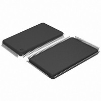
AT91SAM7L64-AU Atmel, AT91SAM7L64-AU Datasheet - Page 562

AT91SAM7L64-AU
Manufacturer Part Number
AT91SAM7L64-AU
Description
MCU ARM7 64K HS FLASH 128-LQFP
Manufacturer
Atmel
Series
AT91SAMr
Specifications of AT91SAM7L64-AU
Core Processor
ARM7
Core Size
16/32-Bit
Speed
36MHz
Connectivity
I²C, SPI, UART/USART
Peripherals
Brown-out Detect/Reset, LCD, POR, PWM, WDT
Number Of I /o
80
Program Memory Size
64KB (64K x 8)
Program Memory Type
FLASH
Ram Size
6K x 8
Voltage - Supply (vcc/vdd)
1.55 V ~ 1.8 V
Data Converters
A/D 4x10b
Oscillator Type
Internal
Operating Temperature
-40°C ~ 85°C
Package / Case
128-LQFP
Controller Family/series
AT91SAM7xxx
No. Of I/o's
80
Ram Memory Size
6KB
Cpu Speed
36MHz
No. Of Timers
1
Rohs Compliant
Yes
Processor Series
AT91SAMx
Core
ARM7TDMI
Data Bus Width
32 bit
Data Ram Size
6 KB
Interface Type
2-Wire, SPI, USART
Maximum Clock Frequency
36 MHz
Number Of Programmable I/os
80
Number Of Timers
3
Maximum Operating Temperature
+ 85 C
Mounting Style
SMD/SMT
3rd Party Development Tools
JTRACE-ARM-2M, MDK-ARM, RL-ARM, ULINK2
Development Tools By Supplier
AT91SAM-ICE, AT91-ISP, AT91SAM7L-EK
Minimum Operating Temperature
- 40 C
On-chip Adc
10 bit, 4 Channel
For Use With
AT91SAM7L-STK - KIT EVAL FOR AT91SAM7LAT91SAM-ICE - EMULATOR FOR AT91 ARM7/ARM9
Lead Free Status / RoHS Status
Lead free / RoHS Compliant
Eeprom Size
-
Lead Free Status / Rohs Status
Details
Available stocks
Company
Part Number
Manufacturer
Quantity
Price
- Current page: 562 of 564
- Download datasheet (9Mb)
vi
AT91SAM7L128/64 Preliminary
30 Universal Synchronous Asynchronous Receiver Transceiver
31 Timer Counter (TC) .............................................................................. 419
32 Pulse Width Modulation Controller (PWM) ........................................ 453
33 Analog-to-Digital Converter (ADC) ..................................................... 473
(USART) ................................................................................................ 361
29.1
29.2
29.3
29.4
29.5
29.6
29.7
29.8
29.9
29.10
30.1
30.2
30.3
30.4
30.5
30.6
30.7
31.1
31.2
31.3
31.4
31.5
31.6
32.1
32.2
32.3
32.4
32.5
32.6
Overview ........................................................................................................319
List of Abbreviations ......................................................................................319
Block Diagram ...............................................................................................320
Application Block Diagram .............................................................................320
Product Dependencies ..................................................................................321
Functional Description ...................................................................................321
Master Mode ..................................................................................................323
Multi-master Mode .........................................................................................335
Slave Mode ....................................................................................................338
Two-wire Interface (TWI) User Interface .......................................................346
Overview ........................................................................................................361
Block Diagram ...............................................................................................362
Application Block Diagram .............................................................................363
I/O Lines Description ....................................................................................364
Product Dependencies ..................................................................................365
Functional Description ...................................................................................366
Universal Synchronous Asynchronous Receiver Transmitter
(USART) User Interface ...............................................................................397
Overview ........................................................................................................419
Block Diagram ...............................................................................................420
Pin Name List ................................................................................................421
Product Dependencies ..................................................................................421
Functional Description ...................................................................................422
Timer Counter (TC) User Interface ................................................................435
Overview ........................................................................................................453
Block Diagram ...............................................................................................453
I/O Lines Description .....................................................................................454
Product Dependencies ..................................................................................454
Functional Description ...................................................................................454
Pulse Width Modulation Controller (PWM) User Interface ............................463
DRAFT
6257A–ATARM–20-Feb-08
Related parts for AT91SAM7L64-AU
Image
Part Number
Description
Manufacturer
Datasheet
Request
R

Part Number:
Description:
KIT EVAL FOR AT91SAM7L
Manufacturer:
Atmel
Datasheet:

Part Number:
Description:
DEV KIT FOR AVR/AVR32
Manufacturer:
Atmel
Datasheet:

Part Number:
Description:
INTERVAL AND WIPE/WASH WIPER CONTROL IC WITH DELAY
Manufacturer:
ATMEL Corporation
Datasheet:

Part Number:
Description:
Low-Voltage Voice-Switched IC for Hands-Free Operation
Manufacturer:
ATMEL Corporation
Datasheet:

Part Number:
Description:
MONOLITHIC INTEGRATED FEATUREPHONE CIRCUIT
Manufacturer:
ATMEL Corporation
Datasheet:

Part Number:
Description:
AM-FM Receiver IC U4255BM-M
Manufacturer:
ATMEL Corporation
Datasheet:

Part Number:
Description:
Monolithic Integrated Feature Phone Circuit
Manufacturer:
ATMEL Corporation
Datasheet:

Part Number:
Description:
Multistandard Video-IF and Quasi Parallel Sound Processing
Manufacturer:
ATMEL Corporation
Datasheet:

Part Number:
Description:
High-performance EE PLD
Manufacturer:
ATMEL Corporation
Datasheet:

Part Number:
Description:
8-bit Flash Microcontroller
Manufacturer:
ATMEL Corporation
Datasheet:

Part Number:
Description:
2-Wire Serial EEPROM
Manufacturer:
ATMEL Corporation
Datasheet:


