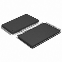
AT91SAM7L64-AU Atmel, AT91SAM7L64-AU Datasheet - Page 220

AT91SAM7L64-AU
Manufacturer Part Number
AT91SAM7L64-AU
Description
MCU ARM7 64K HS FLASH 128-LQFP
Manufacturer
Atmel
Series
AT91SAMr
Specifications of AT91SAM7L64-AU
Core Processor
ARM7
Core Size
16/32-Bit
Speed
36MHz
Connectivity
I²C, SPI, UART/USART
Peripherals
Brown-out Detect/Reset, LCD, POR, PWM, WDT
Number Of I /o
80
Program Memory Size
64KB (64K x 8)
Program Memory Type
FLASH
Ram Size
6K x 8
Voltage - Supply (vcc/vdd)
1.55 V ~ 1.8 V
Data Converters
A/D 4x10b
Oscillator Type
Internal
Operating Temperature
-40°C ~ 85°C
Package / Case
128-LQFP
Controller Family/series
AT91SAM7xxx
No. Of I/o's
80
Ram Memory Size
6KB
Cpu Speed
36MHz
No. Of Timers
1
Rohs Compliant
Yes
Processor Series
AT91SAMx
Core
ARM7TDMI
Data Bus Width
32 bit
Data Ram Size
6 KB
Interface Type
2-Wire, SPI, USART
Maximum Clock Frequency
36 MHz
Number Of Programmable I/os
80
Number Of Timers
3
Maximum Operating Temperature
+ 85 C
Mounting Style
SMD/SMT
3rd Party Development Tools
JTRACE-ARM-2M, MDK-ARM, RL-ARM, ULINK2
Development Tools By Supplier
AT91SAM-ICE, AT91-ISP, AT91SAM7L-EK
Minimum Operating Temperature
- 40 C
On-chip Adc
10 bit, 4 Channel
For Use With
AT91SAM7L-STK - KIT EVAL FOR AT91SAM7LAT91SAM-ICE - EMULATOR FOR AT91 ARM7/ARM9
Lead Free Status / RoHS Status
Lead free / RoHS Compliant
Eeprom Size
-
Lead Free Status / Rohs Status
Details
Available stocks
Company
Part Number
Manufacturer
Quantity
Price
- Current page: 220 of 564
- Download datasheet (9Mb)
25.6
25.7
220
The Fast Startup
Programming Sequence
AT91SAM7L128/64 Preliminary
The SAM7L device allows the processor to restart in less than six microseconds while the device
is in Wait mode. A Fast Startup is enabled upon the detection of a low level on one of the 16
wake-up inputs.
The Fast Restart circuitry, as shown in
startup signal to the Power Management Controller. As soon as the fast startup signal is
asserted, this automatically restarts the embedded 2 MHz Fast RC oscillator, switches the Mas-
ter Clock on the 2 MHz clock and re-enables the processor clock if it is disabled.
Figure 25-2. Fast Startup Circuitry
Each wake-up input pin can be enabled to generate a Fast Startup event by writing at 1 the cor-
responding bit in the Fast Startup Mode Register SUPC_FSMR. Only a low level on the enabled
wake-up input pins generates a Fast Startup.
The user interface does not provide any status for Fast Startup, but the user can easily recover
this information by reading the PIO Controller.
7. Checking the Main Oscillator Frequency (Optional):
8. Setting PLL and divider:
In some situations the user may need an accurate measure of the main clock frequency.
This measure can be accomplished via the CKGR_MCFR register.
Once the MAINFRDY field is set in CKGR_MCFR register, the user may read the MAINF
field in CKGR_MCFR register. This provides the number of main clock cycles within sixteen
slow clock cycles.
All parameters needed to configure PLL and the divider are located in the CKGR_PLLR
register.
The DIV field is used to control the divider itself. It must be set to 1 when PLL is used. By
default, DIV parameter is set to 0 which means that the divider is turned off.
The MUL field is the PLL multiplier factor. This parameter can be programmed between 0
and 2047. If MUL is set to 0, PLL will be turned off, otherwise the PLL output frequency is
PLL input frequency multiplied by (MUL + 1).
WKUP15
WKUP0
WKUP1
FSTT15
FSTT0
FSTT1
Figure
25-2, is fully asynchronous and provides a fast
fast_restart
6257A–ATARM–20-Feb-08
Related parts for AT91SAM7L64-AU
Image
Part Number
Description
Manufacturer
Datasheet
Request
R

Part Number:
Description:
KIT EVAL FOR AT91SAM7L
Manufacturer:
Atmel
Datasheet:

Part Number:
Description:
DEV KIT FOR AVR/AVR32
Manufacturer:
Atmel
Datasheet:

Part Number:
Description:
INTERVAL AND WIPE/WASH WIPER CONTROL IC WITH DELAY
Manufacturer:
ATMEL Corporation
Datasheet:

Part Number:
Description:
Low-Voltage Voice-Switched IC for Hands-Free Operation
Manufacturer:
ATMEL Corporation
Datasheet:

Part Number:
Description:
MONOLITHIC INTEGRATED FEATUREPHONE CIRCUIT
Manufacturer:
ATMEL Corporation
Datasheet:

Part Number:
Description:
AM-FM Receiver IC U4255BM-M
Manufacturer:
ATMEL Corporation
Datasheet:

Part Number:
Description:
Monolithic Integrated Feature Phone Circuit
Manufacturer:
ATMEL Corporation
Datasheet:

Part Number:
Description:
Multistandard Video-IF and Quasi Parallel Sound Processing
Manufacturer:
ATMEL Corporation
Datasheet:

Part Number:
Description:
High-performance EE PLD
Manufacturer:
ATMEL Corporation
Datasheet:

Part Number:
Description:
8-bit Flash Microcontroller
Manufacturer:
ATMEL Corporation
Datasheet:

Part Number:
Description:
2-Wire Serial EEPROM
Manufacturer:
ATMEL Corporation
Datasheet:


