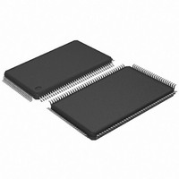
AT91SAM7L64-AU Atmel, AT91SAM7L64-AU Datasheet - Page 195

AT91SAM7L64-AU
Manufacturer Part Number
AT91SAM7L64-AU
Description
MCU ARM7 64K HS FLASH 128-LQFP
Manufacturer
Atmel
Series
AT91SAMr
Specifications of AT91SAM7L64-AU
Core Processor
ARM7
Core Size
16/32-Bit
Speed
36MHz
Connectivity
I²C, SPI, UART/USART
Peripherals
Brown-out Detect/Reset, LCD, POR, PWM, WDT
Number Of I /o
80
Program Memory Size
64KB (64K x 8)
Program Memory Type
FLASH
Ram Size
6K x 8
Voltage - Supply (vcc/vdd)
1.55 V ~ 1.8 V
Data Converters
A/D 4x10b
Oscillator Type
Internal
Operating Temperature
-40°C ~ 85°C
Package / Case
128-LQFP
Controller Family/series
AT91SAM7xxx
No. Of I/o's
80
Ram Memory Size
6KB
Cpu Speed
36MHz
No. Of Timers
1
Rohs Compliant
Yes
Processor Series
AT91SAMx
Core
ARM7TDMI
Data Bus Width
32 bit
Data Ram Size
6 KB
Interface Type
2-Wire, SPI, USART
Maximum Clock Frequency
36 MHz
Number Of Programmable I/os
80
Number Of Timers
3
Maximum Operating Temperature
+ 85 C
Mounting Style
SMD/SMT
3rd Party Development Tools
JTRACE-ARM-2M, MDK-ARM, RL-ARM, ULINK2
Development Tools By Supplier
AT91SAM-ICE, AT91-ISP, AT91SAM7L-EK
Minimum Operating Temperature
- 40 C
On-chip Adc
10 bit, 4 Channel
For Use With
AT91SAM7L-STK - KIT EVAL FOR AT91SAM7LAT91SAM-ICE - EMULATOR FOR AT91 ARM7/ARM9
Lead Free Status / RoHS Status
Lead free / RoHS Compliant
Eeprom Size
-
Lead Free Status / Rohs Status
Details
Available stocks
Company
Part Number
Manufacturer
Quantity
Price
- Current page: 195 of 564
- Download datasheet (9Mb)
23.7.2.3
23.7.2.4
23.7.3
23.7.3.1
6257A–ATARM–20-Feb-08
Normal Interrupt
Internal Interrupt Edge Triggered Source
Internal Interrupt Level Sensitive Source
Priority Controller
Figure 23-8.
Figure 23-9.
An 8-level priority controller drives the nIRQ line of the processor, depending on the interrupt
conditions occurring on the interrupt sources 1 to 31 (except for those programmed in Fast
Forcing).
Each interrupt source has a programmable priority level of 7 to 0, which is user-definable by writ-
ing the PRIOR field of the corresponding AIC_SMR (Source Mode Register). Level 7 is the
highest priority and level 0 the lowest.
As soon as an interrupt condition occurs, as defined by the SRCTYPE field of the AIC_SMR
(Source Mode Register), the nIRQ line is asserted. As a new interrupt condition might have hap-
pened on other interrupt sources since the nIRQ has been asserted, the priority controller
determines the current interrupt at the time the AIC_IVR (Interrupt Vector Register) is read. The
read of AIC_IVR is the entry point of the interrupt handling which allows the AIC to consider
that the interrupt has been taken into account by the software.
The current priority level is defined as the priority level of the current interrupt.
If several interrupt sources of equal priority are pending and enabled when the AIC_IVR is read,
the interrupt with the lowest interrupt source number is serviced first.
Internal Interrupt Edge Triggered Source
Internal Interrupt Level Sensitive Source
nIRQ
MCK
nIRQ
MCK
Peripheral Interrupt
Peripheral Interrupt
Becomes Active
Becomes Active
Maximum IRQ Latency = 4.5 Cycles
AT91SAM7L128/64 Preliminary
Maximum IRQ Latency = 3.5 Cycles
195
Related parts for AT91SAM7L64-AU
Image
Part Number
Description
Manufacturer
Datasheet
Request
R

Part Number:
Description:
KIT EVAL FOR AT91SAM7L
Manufacturer:
Atmel
Datasheet:

Part Number:
Description:
DEV KIT FOR AVR/AVR32
Manufacturer:
Atmel
Datasheet:

Part Number:
Description:
INTERVAL AND WIPE/WASH WIPER CONTROL IC WITH DELAY
Manufacturer:
ATMEL Corporation
Datasheet:

Part Number:
Description:
Low-Voltage Voice-Switched IC for Hands-Free Operation
Manufacturer:
ATMEL Corporation
Datasheet:

Part Number:
Description:
MONOLITHIC INTEGRATED FEATUREPHONE CIRCUIT
Manufacturer:
ATMEL Corporation
Datasheet:

Part Number:
Description:
AM-FM Receiver IC U4255BM-M
Manufacturer:
ATMEL Corporation
Datasheet:

Part Number:
Description:
Monolithic Integrated Feature Phone Circuit
Manufacturer:
ATMEL Corporation
Datasheet:

Part Number:
Description:
Multistandard Video-IF and Quasi Parallel Sound Processing
Manufacturer:
ATMEL Corporation
Datasheet:

Part Number:
Description:
High-performance EE PLD
Manufacturer:
ATMEL Corporation
Datasheet:

Part Number:
Description:
8-bit Flash Microcontroller
Manufacturer:
ATMEL Corporation
Datasheet:

Part Number:
Description:
2-Wire Serial EEPROM
Manufacturer:
ATMEL Corporation
Datasheet:


