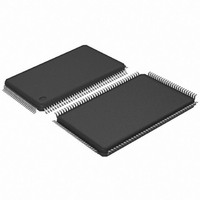
AT91SAM7L64-AU Atmel, AT91SAM7L64-AU Datasheet - Page 372

AT91SAM7L64-AU
Manufacturer Part Number
AT91SAM7L64-AU
Description
MCU ARM7 64K HS FLASH 128-LQFP
Manufacturer
Atmel
Series
AT91SAMr
Specifications of AT91SAM7L64-AU
Core Processor
ARM7
Core Size
16/32-Bit
Speed
36MHz
Connectivity
I²C, SPI, UART/USART
Peripherals
Brown-out Detect/Reset, LCD, POR, PWM, WDT
Number Of I /o
80
Program Memory Size
64KB (64K x 8)
Program Memory Type
FLASH
Ram Size
6K x 8
Voltage - Supply (vcc/vdd)
1.55 V ~ 1.8 V
Data Converters
A/D 4x10b
Oscillator Type
Internal
Operating Temperature
-40°C ~ 85°C
Package / Case
128-LQFP
Controller Family/series
AT91SAM7xxx
No. Of I/o's
80
Ram Memory Size
6KB
Cpu Speed
36MHz
No. Of Timers
1
Rohs Compliant
Yes
Processor Series
AT91SAMx
Core
ARM7TDMI
Data Bus Width
32 bit
Data Ram Size
6 KB
Interface Type
2-Wire, SPI, USART
Maximum Clock Frequency
36 MHz
Number Of Programmable I/os
80
Number Of Timers
3
Maximum Operating Temperature
+ 85 C
Mounting Style
SMD/SMT
3rd Party Development Tools
JTRACE-ARM-2M, MDK-ARM, RL-ARM, ULINK2
Development Tools By Supplier
AT91SAM-ICE, AT91-ISP, AT91SAM7L-EK
Minimum Operating Temperature
- 40 C
On-chip Adc
10 bit, 4 Channel
For Use With
AT91SAM7L-STK - KIT EVAL FOR AT91SAM7LAT91SAM-ICE - EMULATOR FOR AT91 ARM7/ARM9
Lead Free Status / RoHS Status
Lead free / RoHS Compliant
Eeprom Size
-
Lead Free Status / Rohs Status
Details
Available stocks
Company
Part Number
Manufacturer
Quantity
Price
- Current page: 372 of 564
- Download datasheet (9Mb)
30.6.3.2
372
AT91SAM7L128/64 Preliminary
Manchester Encoder
encoded based on biphase Manchester II format. To enable this mode, set the MAN field in the
US_MR register to 1. Depending on polarity configuration, a logic level (zero or one), is transmit-
ted as a coded signal one-to-zero or zero-to-one. Thus, a transition always occurs at the
When the Manchester encoder is in use, characters transmitted through the USART are
ber of stop bits is selected by the NBSTOP field in US_MR. The 1.5 stop bit is supported in
asynchronous mode only.
Figure 30-6. Character Transmit
The characters are sent by writing in the Transmit Holding Register (US_THR). The transmitter
reports two status bits in the Channel Status Register (US_CSR): TXRDY (Transmitter Ready),
which indicates that US_THR is empty and TXEMPTY, which indicates that all the characters
written in US_THR have been processed. When the current character processing is completed,
the last character written in US_THR is transferred into the Shift Register of the transmitter and
US_THR becomes empty, thus TXRDY rises.
Both TXRDY and TXEMPTY bits are low when the transmitter is disabled. Writing a character in
US_THR while TXRDY is low has no effect and the written character is lost.
Figure 30-7. Transmitter Status
midpoint of each bit time. It consumes more bandwidth than the original NRZ signal (2x) but the
receiver has more error control since the expected input must show a change at the center of a
bit cell. An example of Manchester encoded sequence is: the byte 0xB1 or 10110001 encodes
to 10 01 10 10 01 01 01 10, assuming the default polarity of the encoder.
this coding scheme.
Baud Rate
TXEMPTY
Baud Rate
Example: 8-bit, Parity Enabled One Stop
US_THR
TXRDY
Clock
Write
Clock
TXD
TXD
Start
Bit
Start
Bit
D0
D1
D0
D2
D3
D1
D4
D5
D2
D6
D7
D3
Parity
Bit
Stop
Bit
D4
Start
Bit
D0
D5
D1
D2
D6
D3
D4
D7
D5
Figure 30-8
6257A–ATARM–20-Feb-08
D6
Parity
Bit
D7
Parity
Bit
Stop
Bit
Stop
illustrates
Bit
Related parts for AT91SAM7L64-AU
Image
Part Number
Description
Manufacturer
Datasheet
Request
R

Part Number:
Description:
KIT EVAL FOR AT91SAM7L
Manufacturer:
Atmel
Datasheet:

Part Number:
Description:
DEV KIT FOR AVR/AVR32
Manufacturer:
Atmel
Datasheet:

Part Number:
Description:
INTERVAL AND WIPE/WASH WIPER CONTROL IC WITH DELAY
Manufacturer:
ATMEL Corporation
Datasheet:

Part Number:
Description:
Low-Voltage Voice-Switched IC for Hands-Free Operation
Manufacturer:
ATMEL Corporation
Datasheet:

Part Number:
Description:
MONOLITHIC INTEGRATED FEATUREPHONE CIRCUIT
Manufacturer:
ATMEL Corporation
Datasheet:

Part Number:
Description:
AM-FM Receiver IC U4255BM-M
Manufacturer:
ATMEL Corporation
Datasheet:

Part Number:
Description:
Monolithic Integrated Feature Phone Circuit
Manufacturer:
ATMEL Corporation
Datasheet:

Part Number:
Description:
Multistandard Video-IF and Quasi Parallel Sound Processing
Manufacturer:
ATMEL Corporation
Datasheet:

Part Number:
Description:
High-performance EE PLD
Manufacturer:
ATMEL Corporation
Datasheet:

Part Number:
Description:
8-bit Flash Microcontroller
Manufacturer:
ATMEL Corporation
Datasheet:

Part Number:
Description:
2-Wire Serial EEPROM
Manufacturer:
ATMEL Corporation
Datasheet:


