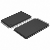
AT91SAM7L64-AU Atmel, AT91SAM7L64-AU Datasheet - Page 15

AT91SAM7L64-AU
Manufacturer Part Number
AT91SAM7L64-AU
Description
MCU ARM7 64K HS FLASH 128-LQFP
Manufacturer
Atmel
Series
AT91SAMr
Specifications of AT91SAM7L64-AU
Core Processor
ARM7
Core Size
16/32-Bit
Speed
36MHz
Connectivity
I²C, SPI, UART/USART
Peripherals
Brown-out Detect/Reset, LCD, POR, PWM, WDT
Number Of I /o
80
Program Memory Size
64KB (64K x 8)
Program Memory Type
FLASH
Ram Size
6K x 8
Voltage - Supply (vcc/vdd)
1.55 V ~ 1.8 V
Data Converters
A/D 4x10b
Oscillator Type
Internal
Operating Temperature
-40°C ~ 85°C
Package / Case
128-LQFP
Controller Family/series
AT91SAM7xxx
No. Of I/o's
80
Ram Memory Size
6KB
Cpu Speed
36MHz
No. Of Timers
1
Rohs Compliant
Yes
Processor Series
AT91SAMx
Core
ARM7TDMI
Data Bus Width
32 bit
Data Ram Size
6 KB
Interface Type
2-Wire, SPI, USART
Maximum Clock Frequency
36 MHz
Number Of Programmable I/os
80
Number Of Timers
3
Maximum Operating Temperature
+ 85 C
Mounting Style
SMD/SMT
3rd Party Development Tools
JTRACE-ARM-2M, MDK-ARM, RL-ARM, ULINK2
Development Tools By Supplier
AT91SAM-ICE, AT91-ISP, AT91SAM7L-EK
Minimum Operating Temperature
- 40 C
On-chip Adc
10 bit, 4 Channel
For Use With
AT91SAM7L-STK - KIT EVAL FOR AT91SAM7LAT91SAM-ICE - EMULATOR FOR AT91 ARM7/ARM9
Lead Free Status / RoHS Status
Lead free / RoHS Compliant
Eeprom Size
-
Lead Free Status / Rohs Status
Details
Available stocks
Company
Part Number
Manufacturer
Quantity
Price
- Current page: 15 of 564
- Download datasheet (9Mb)
5.5
6257A–ATARM–20-Feb-08
Voltage Regulator
Figure 5-2.
The AT91SAM7L128/64 embeds a voltage regulator that is managed by the supply controller.
This internal regulator is only intended to supply the internal core of AT91SAM7L128/64. It fea-
tures three different operating modes:
Furthermore, in normal and deep modes, the regulator output voltage can be programmed by
software with 4 different steps within the range of 1.55V to 1.80V. The default output voltage is
1.80V in both normal and deep modes. The voltage regulator can regulate 1.80V output voltage
as long as the input voltage is above 1.95V. Below 1.95V input voltage, the output voltage
remains above 1.65V.
Output voltage adjusting ability allows current consumption reduction on VDDCORE and also
enables programming a lower voltage when the input voltage is lower than 1.95V.
At 1.55V, the Flash is still functional but with slower read access time. Programming or erasing
the Flash is not possible under these conditions. MCK maximum frequency is 25 MHz with
VDDCORE at 1.55V (1.45V minimum).
The regulator has an indicator that can be used by the software to show that the output voltage
has the correct value (output voltage has reached at least 80% of the typical voltage). This flag
is used by the supply controller. This feature is only possible when the voltage regulator is in
normal mode at 1.80V.
Adequate output supply decoupling is mandatory for VDDOUT in order to reduce ripple and
avoid oscillations. One external 2.2 µF (or 3.3 µF) X7R capacitor must be connected between
VDDOUT and GND.
• In normal mode, the voltage regulator consumes less than 30 µA static current and draws
• In deep mode, the current consumption of the voltage regulator is less than 8.5 µA. It can
• In shutdown mode, the voltage regulator consumes less than 1 µA while its output is driven
60 mA of output current.
draw up to 1 mA of output current. The default output voltage is 1.80V and the start-up time to
reach normal mode is inferior to 400 µs.
internally to GND. The default output voltage is 1.80V and the start-up time to reach normal
mode is inferior to 400 µs.
WKUP15
Fast Start-Up Circuitry
WKUP0
WKUP1
FSTT15
FSTT0
FSTT1
AT91SAM7L128/64 Preliminary
fast_restart
15
Related parts for AT91SAM7L64-AU
Image
Part Number
Description
Manufacturer
Datasheet
Request
R

Part Number:
Description:
KIT EVAL FOR AT91SAM7L
Manufacturer:
Atmel
Datasheet:

Part Number:
Description:
DEV KIT FOR AVR/AVR32
Manufacturer:
Atmel
Datasheet:

Part Number:
Description:
INTERVAL AND WIPE/WASH WIPER CONTROL IC WITH DELAY
Manufacturer:
ATMEL Corporation
Datasheet:

Part Number:
Description:
Low-Voltage Voice-Switched IC for Hands-Free Operation
Manufacturer:
ATMEL Corporation
Datasheet:

Part Number:
Description:
MONOLITHIC INTEGRATED FEATUREPHONE CIRCUIT
Manufacturer:
ATMEL Corporation
Datasheet:

Part Number:
Description:
AM-FM Receiver IC U4255BM-M
Manufacturer:
ATMEL Corporation
Datasheet:

Part Number:
Description:
Monolithic Integrated Feature Phone Circuit
Manufacturer:
ATMEL Corporation
Datasheet:

Part Number:
Description:
Multistandard Video-IF and Quasi Parallel Sound Processing
Manufacturer:
ATMEL Corporation
Datasheet:

Part Number:
Description:
High-performance EE PLD
Manufacturer:
ATMEL Corporation
Datasheet:

Part Number:
Description:
8-bit Flash Microcontroller
Manufacturer:
ATMEL Corporation
Datasheet:

Part Number:
Description:
2-Wire Serial EEPROM
Manufacturer:
ATMEL Corporation
Datasheet:


