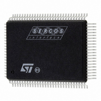
ST92F150CV1QB STMicroelectronics, ST92F150CV1QB Datasheet - Page 413

ST92F150CV1QB
Manufacturer Part Number
ST92F150CV1QB
Description
MCU 8BIT 128K FLASH 100PQFP
Manufacturer
STMicroelectronics
Series
ST9r
Datasheet
1.ST92F150CV1TB.pdf
(429 pages)
Specifications of ST92F150CV1QB
Core Processor
ST9
Core Size
8/16-Bit
Speed
24MHz
Connectivity
CAN, I²C, LIN, SCI, SPI
Peripherals
DMA, LVD, POR, PWM, WDT
Number Of I /o
77
Program Memory Size
128KB (128K x 8)
Program Memory Type
FLASH
Eeprom Size
1K x 8
Ram Size
4K x 8
Voltage - Supply (vcc/vdd)
4.5 V ~ 5.5 V
Data Converters
A/D 16x10b
Oscillator Type
Internal
Operating Temperature
-40°C ~ 105°C
Package / Case
100-QFP
Processor Series
ST92F15x
Core
ST9
Data Bus Width
8 bit, 16 bit
Data Ram Size
6 KB
Interface Type
CAN, I2C, SCI, SPI
Maximum Clock Frequency
24 MHz
Number Of Programmable I/os
80
Number Of Timers
5 x 16 bit
Operating Supply Voltage
4.5 V to 5.5 V
Maximum Operating Temperature
+ 105 C
Mounting Style
SMD/SMT
Development Tools By Supplier
ST92F150-EPB
Minimum Operating Temperature
- 40 C
On-chip Adc
16 bit x 10 bit
Lead Free Status / RoHS Status
Lead free / RoHS Compliant
Other names
497-4882
Available stocks
Company
Part Number
Manufacturer
Quantity
Price
Company:
Part Number:
ST92F150CV1QB
Manufacturer:
STMicroelectronics
Quantity:
10 000
- Current page: 413 of 429
- Download datasheet (8Mb)
KNOWN LIMITATIONS (Cont’d)
13.4 SCI-A AND CAN INTERRUPTS
Description
SCI-A interrupt (I0 channel) and CAN interrupts
(channels E0, E1, F0, F1, G0, G1, H0, H1) do not
respond when the CPUCLK is prescaled (MODER
register).
Workaround
Avoid using CPU prescaler when SCI-A and/or
CAN interrupts are used in the application.
13.5 SCI-A MUTE MODE
13.5.1 Mute Mode Description
The SCI can be put in Mute mode waiting for an
Idle line detection or an Address Mark detection,
and discarding all other byte transmissions. This is
done by setting the RWU (Receiver wake-up) bit in
the SCICR2 register (R244, page 26). This bit can
be reset either by software, to leave the Mute
mode, or by hardware when a wake up condition
has been reached.
Figure 1. Mute Mode Mechanism on address mark
Consequence
The address byte is lost and the SCI-A is again in
Mute mode.
Data Line
RDRF
RWU
Mute mode mechanism
data
int
ST92F124/F150/F250 - KNOWN LIMITATIONS
Data Line
A received data is indicated by the RDRF (Read
Data Ready Flag) bit in the SCISR register (R240,
page 26). This status bit is evaluated at the end of
the stop bit. If the RWU bit is in the set state at the
end of the stop bit, the data is not loaded in the
data register and the RDRF bit is not set.
On the contrary, if the RWU bit is in the reset state
at the end of the stop bit the data is loaded in the
data register and the RDRF bit is set.
13.5.2 Limitation Description
The SCICR2 also contains the following configura-
tion bits: Interrupt Enable, Transmitter Enable, Re-
ceiver Enable and Send Break.
When the value of one of these bits is modified by
software, the SCICR2 register is read, its value is
modified and reloaded in the SCICR2 register. If
the SCI-A is in Mute mode during the read opera-
tion (RWU=1) and if an address mark event occurs
(resetting the RWU bit) before the write operation,
the RWU bit is set before the end of the stop bit. In
this case, the RDRF bit is not set, the data is not
received and no flag indicates the lost of the data.
13.5.3 Workaround
If you need to disable the SCI-A interrupt while it is
in Mute mode, use the global interrupt mask in the
dedicated interrupt controller, refer to Section 5.7
“Standard Interrupts” in the datasheet. Do not
change the TE, RE and SBK bits in the SCICR2
register while the SCI-A is in Mute mode.
RDRF
RWU
Corrupted Mute mode mechanism
ld r0,SCICR2
and r0,0x80
ld SCICR2, r0
under an SCICR2 access
data
413/429
1
Related parts for ST92F150CV1QB
Image
Part Number
Description
Manufacturer
Datasheet
Request
R

Part Number:
Description:
BOARD PROGRAM FOR ST92F150 MCU
Manufacturer:
STMicroelectronics
Datasheet:

Part Number:
Description:
BOARD EVALUATION FOR ST9 SERIES
Manufacturer:
STMicroelectronics
Datasheet:

Part Number:
Description:
BOARD EMULATOR FOR ST9 SERIES
Manufacturer:
STMicroelectronics
Datasheet:

Part Number:
Description:
MCU, MPU & DSP Development Tools ST9 Dedication Board
Manufacturer:
STMicroelectronics
Datasheet:

Part Number:
Description:
STMicroelectronics [RIPPLE-CARRY BINARY COUNTER/DIVIDERS]
Manufacturer:
STMicroelectronics
Datasheet:

Part Number:
Description:
STMicroelectronics [LIQUID-CRYSTAL DISPLAY DRIVERS]
Manufacturer:
STMicroelectronics
Datasheet:

Part Number:
Description:
BOARD EVAL FOR MEMS SENSORS
Manufacturer:
STMicroelectronics
Datasheet:

Part Number:
Description:
NPN TRANSISTOR POWER MODULE
Manufacturer:
STMicroelectronics
Datasheet:

Part Number:
Description:
TURBOSWITCH ULTRA-FAST HIGH VOLTAGE DIODE
Manufacturer:
STMicroelectronics
Datasheet:

Part Number:
Description:
Manufacturer:
STMicroelectronics
Datasheet:

Part Number:
Description:
DIODE / SCR MODULE
Manufacturer:
STMicroelectronics
Datasheet:

Part Number:
Description:
DIODE / SCR MODULE
Manufacturer:
STMicroelectronics
Datasheet:


