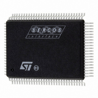
ST92F150CV1QB STMicroelectronics, ST92F150CV1QB Datasheet - Page 134

ST92F150CV1QB
Manufacturer Part Number
ST92F150CV1QB
Description
MCU 8BIT 128K FLASH 100PQFP
Manufacturer
STMicroelectronics
Series
ST9r
Datasheet
1.ST92F150CV1TB.pdf
(429 pages)
Specifications of ST92F150CV1QB
Core Processor
ST9
Core Size
8/16-Bit
Speed
24MHz
Connectivity
CAN, I²C, LIN, SCI, SPI
Peripherals
DMA, LVD, POR, PWM, WDT
Number Of I /o
77
Program Memory Size
128KB (128K x 8)
Program Memory Type
FLASH
Eeprom Size
1K x 8
Ram Size
4K x 8
Voltage - Supply (vcc/vdd)
4.5 V ~ 5.5 V
Data Converters
A/D 16x10b
Oscillator Type
Internal
Operating Temperature
-40°C ~ 105°C
Package / Case
100-QFP
Processor Series
ST92F15x
Core
ST9
Data Bus Width
8 bit, 16 bit
Data Ram Size
6 KB
Interface Type
CAN, I2C, SCI, SPI
Maximum Clock Frequency
24 MHz
Number Of Programmable I/os
80
Number Of Timers
5 x 16 bit
Operating Supply Voltage
4.5 V to 5.5 V
Maximum Operating Temperature
+ 105 C
Mounting Style
SMD/SMT
Development Tools By Supplier
ST92F150-EPB
Minimum Operating Temperature
- 40 C
On-chip Adc
16 bit x 10 bit
Lead Free Status / RoHS Status
Lead free / RoHS Compliant
Other names
497-4882
Available stocks
Company
Part Number
Manufacturer
Quantity
Price
Company:
Part Number:
ST92F150CV1QB
Manufacturer:
STMicroelectronics
Quantity:
10 000
- Current page: 134 of 429
- Download datasheet (8Mb)
ST92F124/F150/F250 - RESET AND CLOCK CONTROL UNIT (RCCU)
7.4 CLOCK CONTROL REGISTERS
MODE REGISTER (MODER)
R235 - Read/Write
System Register
Reset Value: 1110 0000 (E0h)
*Note: This register contains bits which relate to
other functions; these are described in the chapter
dealing with Device Architecture. Only those bits
relating to Clock functions are described here.
Bit 5 = DIV2: Crystal Oscillator Clock Divided by 2.
This bit controls the divide by 2 circuit which oper-
ates on CLOCK1.
0: No division of CLOCK1
1: CLOCK1 is internally divided by 2
Bits 4:2 = PRS[2:0]: Clock Prescaling.
These bits define the prescaler value used to pres-
cale CPUCLK from INTCLK. When these three
bits are reset, the CPUCLK is not prescaled, and is
equal to INTCLK; in all other cases, the internal
clock is prescaled by the value of these three bits
plus one.
CLOCK CONTROL REGISTER (CLKCTL)
R240 - Read/Write
Register Page: 55
Reset Value: 0000 0000 (00h)
Bit 7 = INT_SEL: Interrupt Selection.
0: The external interrupt channel input signal is se-
1: Select the internal RCCU interrupt as the source
Bits 6:4 = Reserved for test purposes
Must be kept reset for normal operation.
Bit 3 = SRESEN: Software Reset Enable.
0: The HALT instruction turns off the quartz, the
1: A Reset is generated when HALT is executed
134/429
9
INT_S
EL
lected (Reset state)
of the interrupt request
PLL and the CCU
7
-
7
-
-
DIV2
-
-
PRS2
SRE-
SEN
PRS1
CKAF_S
EL
PRS0
WFI_CKS
EL
-
LPOW
FI
0
0
-
Bit 2 = CKAF_SEL: Alternate Function Clock Se-
lect.
0: CK_AF clock not selected
1: Select CK_AF clock
Note: To check if the selection has actually oc-
curred, check that CKAF_ST is set. If no clock is
present on the CK_AF pin, the selection will not
occur.
Bit 1 = WFI_CKSEL: WFI Clock Select.
This bit selects the clock used in Low power WFI
mode if LPOWFI = 1.
0: INTCLK during WFI is CLOCK2/16
1: INTCLK during WFI is CK_AF, providing it is
WARNING: When the CK_AF is selected as Low
Power WFI clock but the crystal is not turned off
(R242.4 = 0), after exiting from the WFI, CK_AF
will be still selected as system clock. In this case,
reset the R240.2 bit to switch back to the crystal
oscillator clock.
Bit 0 = LPOWFI: Low Power mode during Wait For
0: Low Power mode during WFI disabled. When
1: The ST9 enters Low Power mode when the WFI
VOLTAGE REGULATOR CONTROL REGISTER
(VRCTR)
R241 - Read/Write
Register Page: 55
Reset Value: 0000 0x00 (0xh)
Bit 7-4 = Reserved, must be kept at 0.
Bit 3 = VROFF_REG: Voltage Regulator OFF
state. This bit is set and cleared by software.
0: Main Voltage Regulator (VR) on
1: Main VR off. In this state the Main Regulator has
This bit must be set for the RTC mode.
Bit 2 = Reserved.
Bit 1-0 = Reserved, must be kept at 0.
present. In effect this bit sets CKAF_SEL in WFI
mode
Interrupt.
WFI is executed, the CPUCLK is stopped and
INTCLK is unchanged
instruction is executed. The clock during this
state depends on WFI_CKSEL
zero power consumption, and the PLL is auto-
matically deselected.
7
0
0
0
0
VROFF
_REG
-
0
0
0
Related parts for ST92F150CV1QB
Image
Part Number
Description
Manufacturer
Datasheet
Request
R

Part Number:
Description:
BOARD PROGRAM FOR ST92F150 MCU
Manufacturer:
STMicroelectronics
Datasheet:

Part Number:
Description:
BOARD EVALUATION FOR ST9 SERIES
Manufacturer:
STMicroelectronics
Datasheet:

Part Number:
Description:
BOARD EMULATOR FOR ST9 SERIES
Manufacturer:
STMicroelectronics
Datasheet:

Part Number:
Description:
MCU, MPU & DSP Development Tools ST9 Dedication Board
Manufacturer:
STMicroelectronics
Datasheet:

Part Number:
Description:
STMicroelectronics [RIPPLE-CARRY BINARY COUNTER/DIVIDERS]
Manufacturer:
STMicroelectronics
Datasheet:

Part Number:
Description:
STMicroelectronics [LIQUID-CRYSTAL DISPLAY DRIVERS]
Manufacturer:
STMicroelectronics
Datasheet:

Part Number:
Description:
BOARD EVAL FOR MEMS SENSORS
Manufacturer:
STMicroelectronics
Datasheet:

Part Number:
Description:
NPN TRANSISTOR POWER MODULE
Manufacturer:
STMicroelectronics
Datasheet:

Part Number:
Description:
TURBOSWITCH ULTRA-FAST HIGH VOLTAGE DIODE
Manufacturer:
STMicroelectronics
Datasheet:

Part Number:
Description:
Manufacturer:
STMicroelectronics
Datasheet:

Part Number:
Description:
DIODE / SCR MODULE
Manufacturer:
STMicroelectronics
Datasheet:

Part Number:
Description:
DIODE / SCR MODULE
Manufacturer:
STMicroelectronics
Datasheet:


