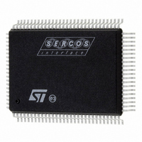
ST92F150CV1QB STMicroelectronics, ST92F150CV1QB Datasheet - Page 139

ST92F150CV1QB
Manufacturer Part Number
ST92F150CV1QB
Description
MCU 8BIT 128K FLASH 100PQFP
Manufacturer
STMicroelectronics
Series
ST9r
Datasheet
1.ST92F150CV1TB.pdf
(429 pages)
Specifications of ST92F150CV1QB
Core Processor
ST9
Core Size
8/16-Bit
Speed
24MHz
Connectivity
CAN, I²C, LIN, SCI, SPI
Peripherals
DMA, LVD, POR, PWM, WDT
Number Of I /o
77
Program Memory Size
128KB (128K x 8)
Program Memory Type
FLASH
Eeprom Size
1K x 8
Ram Size
4K x 8
Voltage - Supply (vcc/vdd)
4.5 V ~ 5.5 V
Data Converters
A/D 16x10b
Oscillator Type
Internal
Operating Temperature
-40°C ~ 105°C
Package / Case
100-QFP
Processor Series
ST92F15x
Core
ST9
Data Bus Width
8 bit, 16 bit
Data Ram Size
6 KB
Interface Type
CAN, I2C, SCI, SPI
Maximum Clock Frequency
24 MHz
Number Of Programmable I/os
80
Number Of Timers
5 x 16 bit
Operating Supply Voltage
4.5 V to 5.5 V
Maximum Operating Temperature
+ 105 C
Mounting Style
SMD/SMT
Development Tools By Supplier
ST92F150-EPB
Minimum Operating Temperature
- 40 C
On-chip Adc
16 bit x 10 bit
Lead Free Status / RoHS Status
Lead free / RoHS Compliant
Other names
497-4882
Available stocks
Company
Part Number
Manufacturer
Quantity
Price
Company:
Part Number:
ST92F150CV1QB
Manufacturer:
STMicroelectronics
Quantity:
10 000
- Current page: 139 of 429
- Download datasheet (8Mb)
CERAMIC RESONATORS
Murata Electronics CERALOCK resonators have been tested with the ST92F150 at 3, 3.68, 4 and 5 MHz.
These recommended resonators have built-in capacitors (see
The test circuit is shown in
Figure 69. Test Circuit
Table 32
Table 32. Obtained Results
Advantages of using ceramic resonators:
CSTCR and CSTCC types have built-in loading
capacitors.
Smallest loading capacitor resonators are recom-
mended for standard applications.
Highest loading capacitor resonators are recom-
mended for automotive applications with CAN and
tight frequency tolerance.
Test conditions:
The evaluation conditions are 4.5 to 5.5 V for the
supply voltage and -40° to 105° C for the tempera-
ture range.
Caution:
These circuit conditions are for design reference
only.
Recommended C1, C2 value depends on the cir-
cuit board used.
(MHz)
Freq.
3.68
5
4
3
shows the recommended conditions at different frequencies.
CSTCR5M00G55A-R0
CSTCC5M00G56A-R0
CSTCR4M00G55A-R0
CSTCC4M00G56A-R0
CSTCC3M00G56A-R0
CSTCC3M68G56A-R0
ST92F124/F150/F250 - RESET AND CLOCK CONTROL UNIT (RCCU)
Parts Number
Figure
69.
V
OSCIN
DD
CERALOCK
C1
ST92F150
C2
OSCOUT
For tight frequency tolerance applications, please
contact the nearest Murata office for more de-
tailled PCB evaluation regarding layout.
Note 1:
Attention must be paid to leakage currents around
the OSCIN pin. Leakage paths from V
ter the DC polarization of the inverter stage and in-
troduce a mismatch with the second stage, and
possibly stop the clock signal. It is recommended
to surround the oscillator components by a ground
ring on the printed circuit board and if necessary to
apply a coating film to avoid humidity problems.
Note 2:
Attention must be paid to the capacitive loading of
OSCOUT. OSCOUT must not be used to drive ex-
ternal circuits.
Rd
C1 (pF)
39
47
39
47
47
47
Table
V
32).
SS
C2 (pF)
39
47
39
47
47
47
Rd (Ohm)
DD
0
0
0
0
0
0
could al-
139/429
9
Related parts for ST92F150CV1QB
Image
Part Number
Description
Manufacturer
Datasheet
Request
R

Part Number:
Description:
BOARD PROGRAM FOR ST92F150 MCU
Manufacturer:
STMicroelectronics
Datasheet:

Part Number:
Description:
BOARD EVALUATION FOR ST9 SERIES
Manufacturer:
STMicroelectronics
Datasheet:

Part Number:
Description:
BOARD EMULATOR FOR ST9 SERIES
Manufacturer:
STMicroelectronics
Datasheet:

Part Number:
Description:
MCU, MPU & DSP Development Tools ST9 Dedication Board
Manufacturer:
STMicroelectronics
Datasheet:

Part Number:
Description:
STMicroelectronics [RIPPLE-CARRY BINARY COUNTER/DIVIDERS]
Manufacturer:
STMicroelectronics
Datasheet:

Part Number:
Description:
STMicroelectronics [LIQUID-CRYSTAL DISPLAY DRIVERS]
Manufacturer:
STMicroelectronics
Datasheet:

Part Number:
Description:
BOARD EVAL FOR MEMS SENSORS
Manufacturer:
STMicroelectronics
Datasheet:

Part Number:
Description:
NPN TRANSISTOR POWER MODULE
Manufacturer:
STMicroelectronics
Datasheet:

Part Number:
Description:
TURBOSWITCH ULTRA-FAST HIGH VOLTAGE DIODE
Manufacturer:
STMicroelectronics
Datasheet:

Part Number:
Description:
Manufacturer:
STMicroelectronics
Datasheet:

Part Number:
Description:
DIODE / SCR MODULE
Manufacturer:
STMicroelectronics
Datasheet:

Part Number:
Description:
DIODE / SCR MODULE
Manufacturer:
STMicroelectronics
Datasheet:


