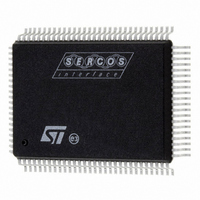
ST92F150CV1QB STMicroelectronics, ST92F150CV1QB Datasheet - Page 161

ST92F150CV1QB
Manufacturer Part Number
ST92F150CV1QB
Description
MCU 8BIT 128K FLASH 100PQFP
Manufacturer
STMicroelectronics
Series
ST9r
Datasheet
1.ST92F150CV1TB.pdf
(429 pages)
Specifications of ST92F150CV1QB
Core Processor
ST9
Core Size
8/16-Bit
Speed
24MHz
Connectivity
CAN, I²C, LIN, SCI, SPI
Peripherals
DMA, LVD, POR, PWM, WDT
Number Of I /o
77
Program Memory Size
128KB (128K x 8)
Program Memory Type
FLASH
Eeprom Size
1K x 8
Ram Size
4K x 8
Voltage - Supply (vcc/vdd)
4.5 V ~ 5.5 V
Data Converters
A/D 16x10b
Oscillator Type
Internal
Operating Temperature
-40°C ~ 105°C
Package / Case
100-QFP
Processor Series
ST92F15x
Core
ST9
Data Bus Width
8 bit, 16 bit
Data Ram Size
6 KB
Interface Type
CAN, I2C, SCI, SPI
Maximum Clock Frequency
24 MHz
Number Of Programmable I/os
80
Number Of Timers
5 x 16 bit
Operating Supply Voltage
4.5 V to 5.5 V
Maximum Operating Temperature
+ 105 C
Mounting Style
SMD/SMT
Development Tools By Supplier
ST92F150-EPB
Minimum Operating Temperature
- 40 C
On-chip Adc
16 bit x 10 bit
Lead Free Status / RoHS Status
Lead free / RoHS Compliant
Other names
497-4882
Available stocks
Company
Part Number
Manufacturer
Quantity
Price
Company:
Part Number:
ST92F150CV1QB
Manufacturer:
STMicroelectronics
Quantity:
10 000
- Current page: 161 of 429
- Download datasheet (8Mb)
TIMER/WATCHDOG (Cont’d)
10.1.4 WDT Interrupts
The Timer/Watchdog issues an interrupt request
at every End of Count, when this feature is ena-
bled.
A pair of control bits, IA0S (EIVR.1, Interrupt A0 se-
lection bit) and TLIS (EIVR.2, Top Level Input Se-
lection bit) allow the selection of 2 interrupt sources
(Timer/Watchdog End of Count, or External Pin)
handled in two different ways, as a Top Level Non
Maskable Interrupt (Software Reset), or as a
source for channel A0 of the external interrupt logic.
A block diagram of the interrupt logic is given in
Figure
Note: Software traps can be generated by setting
the appropriate interrupt pending bit.
Table 34
tions of interrupt/reset sources which relate to the
Timer/Watchdog.
A reset caused by the watchdog will set bit 6,
WDGRES of R242 - Page 55 (Clock Flag Regis-
ter). See
TERS.
Table 34. Interrupt Configuration
Legend:
WDG = Watchdog function
SW TRAP = Software Trap
Note: If IA0S and TLIS = 0 (enabling the Watchdog EOC as interrupt source for both Top Level and INTA0
interrupts), only the INTA0 interrupt is taken into account.
WDGEN
89.
0
0
0
0
1
1
1
1
below, shows all the possible configura-
section CLOCK CONTROL REGIS-
Control Bits
IA0S
0
0
1
1
0
0
1
1
TLIS
0
1
0
1
0
1
0
1
WDG/Ext Reset
WDG/Ext Reset
WDG/Ext Reset
WDG/Ext Reset
Ext Reset
Ext Reset
Ext Reset
Ext Reset
Reset
Enabled Sources
Figure 89. Interrupt Sources
INT0
NMI
SW TRAP
SW TRAP
Ext Pin
Ext Pin
Ext Pin
Ext Pin
INTA0
Timer
Timer
TIMER WATCHDOG
TIMER/WATCHDOG (WDT)
0
1
0
1
MUX
MUX
Top Level
SW TRAP
SW TRAP
Ext Pin
Ext Pin
Ext Pin
Ext Pin
Timer
Timer
TLIS (EIVR.2)
IA0S (EIVR.1)
WDGEN (WCR.6)
INTERRUPT REQUEST
RESET
INTA0 REQUEST
Operating Mode
TOP LEVEL
Watchdog
Watchdog
Watchdog
Watchdog
Timer
Timer
Timer
Timer
VA00293
161/429
9
Related parts for ST92F150CV1QB
Image
Part Number
Description
Manufacturer
Datasheet
Request
R

Part Number:
Description:
BOARD PROGRAM FOR ST92F150 MCU
Manufacturer:
STMicroelectronics
Datasheet:

Part Number:
Description:
BOARD EVALUATION FOR ST9 SERIES
Manufacturer:
STMicroelectronics
Datasheet:

Part Number:
Description:
BOARD EMULATOR FOR ST9 SERIES
Manufacturer:
STMicroelectronics
Datasheet:

Part Number:
Description:
MCU, MPU & DSP Development Tools ST9 Dedication Board
Manufacturer:
STMicroelectronics
Datasheet:

Part Number:
Description:
STMicroelectronics [RIPPLE-CARRY BINARY COUNTER/DIVIDERS]
Manufacturer:
STMicroelectronics
Datasheet:

Part Number:
Description:
STMicroelectronics [LIQUID-CRYSTAL DISPLAY DRIVERS]
Manufacturer:
STMicroelectronics
Datasheet:

Part Number:
Description:
BOARD EVAL FOR MEMS SENSORS
Manufacturer:
STMicroelectronics
Datasheet:

Part Number:
Description:
NPN TRANSISTOR POWER MODULE
Manufacturer:
STMicroelectronics
Datasheet:

Part Number:
Description:
TURBOSWITCH ULTRA-FAST HIGH VOLTAGE DIODE
Manufacturer:
STMicroelectronics
Datasheet:

Part Number:
Description:
Manufacturer:
STMicroelectronics
Datasheet:

Part Number:
Description:
DIODE / SCR MODULE
Manufacturer:
STMicroelectronics
Datasheet:

Part Number:
Description:
DIODE / SCR MODULE
Manufacturer:
STMicroelectronics
Datasheet:


