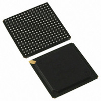
PI7C9X130DNDE Pericom Semiconductor, PI7C9X130DNDE Datasheet - Page 24

PI7C9X130DNDE
Manufacturer Part Number
PI7C9X130DNDE
Description
IC PCIE-PCIX BRIDGE 1PORT 256BGA
Manufacturer
Pericom Semiconductor
Specifications of PI7C9X130DNDE
Applications
PCI-to-PCI Bridge
Interface
SMBus (2-Wire/I²C)
Voltage - Supply
1.8V, 3.3V
Package / Case
256-PBGA
Mounting Type
Surface Mount
Operating Temperature (min)
-40C
Operating Temperature Classification
Industrial
Operating Temperature (max)
85C
Package Type
BGA
Rad Hardened
No
Lead Free Status / RoHS Status
Lead free / RoHS Compliant
Available stocks
Company
Part Number
Manufacturer
Quantity
Price
Company:
Part Number:
PI7C9X130DNDE
Manufacturer:
Pericom
Quantity:
135
Company:
Part Number:
PI7C9X130DNDE
Manufacturer:
NSC
Quantity:
70
3 MODE SELECTION AND PIN STRAPPING
3.1 FUNCTIONAL MODE SELECTION
3.2 PCI/PCI-X SELECTION
PERICOM SEMICONDUCTOR - Confidential
If TM2 is strapped to low, PI7C9X130 uses TM1, TM0, CFN_L, and REVRSB pins to select different
modes of operations. These four input signals are required to be stable during normal operation. One
of the sixteen combinations of normal operation can be selected by setting the logic values for the four
mode select pins. For example, if the logic values are low for all four (TM1, TM0, CFN_L, and
REVRSB) pins, the normal operation will have EEPROM (I2C) support in transparent mode with
internal arbiter in forward bridge mode. The designated operation with respect to the values of the TM1,
TM0, CFN_L, and REVRSB pins are defined on Table 3-1:
Figure 3-3 Functional Mode Selection
The secondary interface is capable of operating in either conventional PCI mode or in PCI-X mode.
PI7C9X130 controls the mode and frequency for the secondary bus by utilizing a pull-up circuit
connected to PCIXCAP. There are two pull-up resistors in the circuit as recommended by the PCI-X
addendum. The first resistor is a weak pull-up (56K ohms) whose value is selected to set the voltage of
PCIXCAP below its low threshold when a PCI-X 66MHz device is attached to the secondary bus. The
second resistor is a strong pull-up, externally wired between PCIXCAP and PCIXUP. The value of the
resistor (1K ohm) is selected to set the voltage of PCIXCAP above its high threshold when all devices on
the secondary are PCI-X 66MHz capable. To detect the mode and frequency of the secondary bus,
PCIXUP is initially disabled and PI7C9X130 samples the value on PCIXCAP.
If PI7C9X130 sees logic LOW on PCIXCAP, one or more devices on the secondary have either pulled
the signal to ground (PCI-X 66MHz capable) or tied it to ground (only capable of conventional PCI
mode). To differentiate between the two conditions, PI7C9X130 then enables PCIXUP to put the
strong pull-up into the circuit node. If PCIXCAP remains at logic LOW, it must be tied to ground by
one or more devices, and the bus is initialized to conventional PCI mode. If PCIXUP can be pulled up,
one or more devices are capable of only PCI-X 66MHz operation so the bus is initialized to PCI-X
66MHz mode. If PI7C9X130 sees logic HIGH on PCIXCAP, then all devices on the secondary bus are
capable of PCI-X 100MHz or 133MHz operation. PI7C9X130 then samples SEL100 to distinguish
between the 100MHz and 133MHz clock frequencies. If PI7C9X130 sees logic HIGH on SEL100, the
secondary bus is initialized to PCI-X 100MHz mode. If the value is LOW, PCI-X 133MHz is initialized.
These two clock frequencies allow the flexibility to support different bus loading conditions.
Strapped
TM2
0
0
0
0
0
0
0
0
TM1
X
X
X
X
X
X
0
1
Page 24 of 165
TM0
X
X
X
X
X
X
0
1
CFN_L
X
X
X
X
X
X
0
1
REVRSB
PCI EXPRESS TO PCI-X BRIDGE
X
X
X
X
X
X
0
1
Mar 2010 - Rev 2.0
EEPROM (I2C) support
SM Bus support
Transparent mode
Non-Transparent mode
Internal arbiter
External arbiter
Forward bridge mode
Reverse bridge mode
Functional Mode
PI7C9X130


