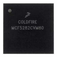
MCF5282CVM80 Freescale Semiconductor, MCF5282CVM80 Datasheet - Page 465

MCF5282CVM80
Manufacturer Part Number
MCF5282CVM80
Description
IC MPU 512K 80MHZ 256-MAPBGA
Manufacturer
Freescale Semiconductor
Series
MCF528xr
Datasheet
1.MCF5216CVM66J.pdf
(766 pages)
Specifications of MCF5282CVM80
Core Processor
Coldfire V2
Core Size
32-Bit
Speed
80MHz
Connectivity
CAN, EBI/EMI, Ethernet, I²C, SPI, UART/USART
Peripherals
DMA, LVD, POR, PWM, WDT
Number Of I /o
150
Program Memory Size
512KB (512K x 8)
Program Memory Type
FLASH
Ram Size
64K x 8
Voltage - Supply (vcc/vdd)
2.7 V ~ 3.6 V
Data Converters
A/D 8x10b
Oscillator Type
External
Operating Temperature
-40°C ~ 85°C
Package / Case
256-MAPBGA
Controller Family/series
ColdFire
Ram Memory Size
64KB
Embedded Interface Type
CAN, I2C, SPI, UART
No. Of Pwm Channels
8
Digital Ic Case Style
MAPBGA
Rohs Compliant
Yes
Lead Free Status / RoHS Status
Lead free / RoHS Compliant
Eeprom Size
-
Available stocks
Company
Part Number
Manufacturer
Quantity
Price
Company:
Part Number:
MCF5282CVM80
Manufacturer:
FREESCALE
Quantity:
1 831
Company:
Part Number:
MCF5282CVM80
Manufacturer:
Freescale Semiconductor
Quantity:
10 000
Company:
Part Number:
MCF5282CVM80J
Manufacturer:
Freescale Semiconductor
Quantity:
10 000
- Current page: 465 of 766
- Download datasheet (9Mb)
24.3.7
I
devices simultaneously request control of the bus, a clock synchronization procedure determines the bus
clock. Because wire-AND logic is performed on the I2C_SCL line, a high-to-low transition on the
I2C_SCL line affects all the devices connected on the bus. The devices start counting their low period and
after a device’s clock has gone low, it holds the I2C_SCL line low until the clock high state is reached.
However, change of low to high in this device’s clock may not change the state of the I2C_SCL line if
another device clock remains within its low period. Therefore, synchronized clock I2C_SCL is held low
by the device with the longest low period.
Devices with shorter low periods enter a high wait state during this time (see
devices concerned have counted off their low period, the synchronized clock (I2C_SCL) line is released
and pulled high. At this point, the device clocks and the I2C_SCL line are synchronized, and the devices
start counting their high periods. The first device to complete its high period pulls the I2C_SCL line low
again.
A data arbitration procedure determines the relative priority of the contending masters. A bus master loses
arbitration if it transmits logic 1 while another master transmits logic 0. The losing masters immediately
switch over to slave receive mode and stop driving I2C_SDA output (see
transition from master to slave mode does not generate a STOP condition. Meanwhile, hardware sets
I2SR[IAL] to indicate loss of arbitration.
Freescale Semiconductor
2
C is a true multi-master bus that allows more than one master connected to it. If two or more master
I2C_SCL1
I2C_SCL2
I2C_SCL
I2C_SDA by
Master1
I2C_SDA by
Master2
I2C_SDA
I2C_SCL
Clock Synchronization and Arbitration
MCF5282 and MCF5216 ColdFire Microcontroller User’s Manual, Rev. 3
Internal Counter Reset
Figure 24-12. Clock Synchronization
Figure 24-13. Arbitration Procedure
Wait
Master 2 Loses Arbitration,
and becomes slave-receiver
Start counting high period
Figure
Figure
24-13). In this case,
24-12). When all
I
2
C Interface
24-11
Related parts for MCF5282CVM80
Image
Part Number
Description
Manufacturer
Datasheet
Request
R
Part Number:
Description:
Mcf5282 And Mcf5216 Coldfire Microcontroller Userís Manual
Manufacturer:
Freescale Semiconductor, Inc
Datasheet:
Part Number:
Description:
Manufacturer:
Freescale Semiconductor, Inc
Datasheet:
Part Number:
Description:
Manufacturer:
Freescale Semiconductor, Inc
Datasheet:
Part Number:
Description:
Manufacturer:
Freescale Semiconductor, Inc
Datasheet:
Part Number:
Description:
Manufacturer:
Freescale Semiconductor, Inc
Datasheet:
Part Number:
Description:
Manufacturer:
Freescale Semiconductor, Inc
Datasheet:
Part Number:
Description:
Manufacturer:
Freescale Semiconductor, Inc
Datasheet:
Part Number:
Description:
Manufacturer:
Freescale Semiconductor, Inc
Datasheet:
Part Number:
Description:
Manufacturer:
Freescale Semiconductor, Inc
Datasheet:
Part Number:
Description:
Manufacturer:
Freescale Semiconductor, Inc
Datasheet:
Part Number:
Description:
Manufacturer:
Freescale Semiconductor, Inc
Datasheet:
Part Number:
Description:
Manufacturer:
Freescale Semiconductor, Inc
Datasheet:
Part Number:
Description:
Manufacturer:
Freescale Semiconductor, Inc
Datasheet:
Part Number:
Description:
Manufacturer:
Freescale Semiconductor, Inc
Datasheet:
Part Number:
Description:
Manufacturer:
Freescale Semiconductor, Inc
Datasheet:


