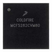
MCF5282CVM80 Freescale Semiconductor, MCF5282CVM80 Datasheet - Page 307

MCF5282CVM80
Manufacturer Part Number
MCF5282CVM80
Description
IC MPU 512K 80MHZ 256-MAPBGA
Manufacturer
Freescale Semiconductor
Series
MCF528xr
Datasheet
1.MCF5216CVM66J.pdf
(766 pages)
Specifications of MCF5282CVM80
Core Processor
Coldfire V2
Core Size
32-Bit
Speed
80MHz
Connectivity
CAN, EBI/EMI, Ethernet, I²C, SPI, UART/USART
Peripherals
DMA, LVD, POR, PWM, WDT
Number Of I /o
150
Program Memory Size
512KB (512K x 8)
Program Memory Type
FLASH
Ram Size
64K x 8
Voltage - Supply (vcc/vdd)
2.7 V ~ 3.6 V
Data Converters
A/D 8x10b
Oscillator Type
External
Operating Temperature
-40°C ~ 85°C
Package / Case
256-MAPBGA
Controller Family/series
ColdFire
Ram Memory Size
64KB
Embedded Interface Type
CAN, I2C, SPI, UART
No. Of Pwm Channels
8
Digital Ic Case Style
MAPBGA
Rohs Compliant
Yes
Lead Free Status / RoHS Status
Lead free / RoHS Compliant
Eeprom Size
-
Available stocks
Company
Part Number
Manufacturer
Quantity
Price
Company:
Part Number:
MCF5282CVM80
Manufacturer:
FREESCALE
Quantity:
1 831
Company:
Part Number:
MCF5282CVM80
Manufacturer:
Freescale Semiconductor
Quantity:
10 000
Company:
Part Number:
MCF5282CVM80J
Manufacturer:
Freescale Semiconductor
Quantity:
10 000
- Current page: 307 of 766
- Download datasheet (9Mb)
16.5
In the following discussion, the term “DMA request” implies that DCRn[START] or DCRn[EEXT] is set,
followed by assertion of DREQn. The START bit is cleared when the channel begins an internal access.
Before initiating a dual-address access, the DMA module verifies that DCRn[SSIZE,DSIZE] are
consistent with the source and destination addresses. If they are not consistent, the configuration error bit,
DSRn[CE], is set. If misalignment is detected, no transfer occurs, DSRn[CE] is set, and, depending on the
DCR configuration, an interrupt event is issued. Note that if the auto-align bit, DCRn[AA], is set, error
checking is performed on the appropriate registers.
A read/write transfer reads bytes from the source address and writes them to the destination address. The
number of bytes is the larger of the sizes specified by DCRn[SSIZE] and DCRn[DSIZE]. See
Section 16.4.4, “DMA Control Registers
Source and destination address registers (SARn and DARn) can be programmed in the DCRn to increment
at the completion of a successful transfer.
16.5.1
The DMA channel supports internal and external requests. A request is issued by setting DCRn[START]
or by asserting DREQn. Setting DCRn[EEXT] enables recognition of external DMA requests. Selecting
between cycle-steal and continuous modes minimizes bus usage for either internal or external requests.
Freescale Semiconductor
•
•
Bits
1
0
Cycle-steal mode (DCRn[CS] = 1)—Only one complete transfer from source to destination occurs
for each request. If DCRn[EEXT] is set, a request can be either internal or external. An internal
request is selected by setting DCRn[START]. An external request is initiated by asserting DREQn
while DCRn[EEXT] is set. Note that multiple transfers will occur if DREQn is continuously
asserted.
Continuous mode (DCRn[CS] = 0)—After an internal or external request, the DMA continuously
transfers data until BCRn reaches zero or a multiple of DCRn[BWC] or until DSRn[DONE] is set.
If BCRn is a multiple of BWC, the DMA request signal is negated until the bus cycle terminates
to allow the internal arbiter to switch masters. DCRn[BWC] = 000 specifies the maximum transfer
rate; other values specify a transfer rate limit.
The DMA performs the specified number of transfers, then relinquishes bus control. The DMA
negates its internal bus request on the last transfer before BCRn reaches a multiple of the boundary
specified in BWC. On completion, the DMA reasserts its bus request to regain mastership at the
earliest opportunity. The DMA loses bus control for a minimum of one bus cycle.
DMA Controller Module Functional Description
Transfer Requests (Cycle-Steal and Continuous Modes)
DONE
Name
BSY
Busy
0 DMA channel is inactive. Cleared when the DMA has finished the last transaction.
1 BSY is set the first time the channel is enabled after a transfer is initiated.
Transactions done. Set when all DMA controller transactions complete, as determined by transfer
count or error conditions. When BCR reaches zero, DONE is set when the final transfer completes
successfully. DONE can also be used to abort a transfer by resetting the status bits. When a transfer
completes, software must clear DONE before reprogramming the DMA.
0 Writing or reading a 0 has no effect.
1 DMA transfer completed. Writing a 1 to this bit clears all DMA status bits and can be used in an
interrupt handler to clear the DMA interrupt and error bits.
MCF5282 and MCF5216 ColdFire Microcontroller User’s Manual, Rev. 3
Table 16-4. DSRn Field Descriptions (continued)
(DCR0–DCR3).”
Description
DMA Controller Module
16-11
Related parts for MCF5282CVM80
Image
Part Number
Description
Manufacturer
Datasheet
Request
R
Part Number:
Description:
Mcf5282 And Mcf5216 Coldfire Microcontroller Userís Manual
Manufacturer:
Freescale Semiconductor, Inc
Datasheet:
Part Number:
Description:
Manufacturer:
Freescale Semiconductor, Inc
Datasheet:
Part Number:
Description:
Manufacturer:
Freescale Semiconductor, Inc
Datasheet:
Part Number:
Description:
Manufacturer:
Freescale Semiconductor, Inc
Datasheet:
Part Number:
Description:
Manufacturer:
Freescale Semiconductor, Inc
Datasheet:
Part Number:
Description:
Manufacturer:
Freescale Semiconductor, Inc
Datasheet:
Part Number:
Description:
Manufacturer:
Freescale Semiconductor, Inc
Datasheet:
Part Number:
Description:
Manufacturer:
Freescale Semiconductor, Inc
Datasheet:
Part Number:
Description:
Manufacturer:
Freescale Semiconductor, Inc
Datasheet:
Part Number:
Description:
Manufacturer:
Freescale Semiconductor, Inc
Datasheet:
Part Number:
Description:
Manufacturer:
Freescale Semiconductor, Inc
Datasheet:
Part Number:
Description:
Manufacturer:
Freescale Semiconductor, Inc
Datasheet:
Part Number:
Description:
Manufacturer:
Freescale Semiconductor, Inc
Datasheet:
Part Number:
Description:
Manufacturer:
Freescale Semiconductor, Inc
Datasheet:
Part Number:
Description:
Manufacturer:
Freescale Semiconductor, Inc
Datasheet:


