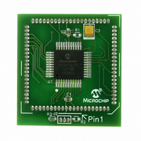
MA180023 Microchip Technology, MA180023 Datasheet - Page 34

MA180023
Manufacturer Part Number
MA180023
Description
MODULE PLUG-IN PIC18F46J11 PIM
Manufacturer
Microchip Technology
Series
PIC®r
Datasheet
1.MA180023.pdf
(528 pages)
Specifications of MA180023
Accessory Type
Plug-In Module (PIM) - PIC18F46J11
Tool / Board Applications
General Purpose MCU, MPU, DSP, DSC
Mcu Supported Families
PIC18
Supported Devices
Stand-alone Or W/ HPC(DM183022) Or PIC18(DM183032)
Silicon Manufacturer
Microchip
Core Architecture
PIC
Core Sub-architecture
PIC18
Silicon Core Number
PIC18F
Silicon Family Name
PIC18FxxJxx
Lead Free Status / RoHS Status
Lead free / RoHS Compliant
For Use With/related Products
HPC Explorer Board (DM183022) or PIC18 Explorer Board (DM183032)
For Use With
DM183032 - BOARD EXPLORER PICDEM PIC18DM183022 - BOARD DEMO PIC18FXX22 64/80TQFP
Lead Free Status / RoHS Status
Lead free / RoHS Compliant
Available stocks
Company
Part Number
Manufacturer
Quantity
Price
Company:
Part Number:
MA180023
Manufacturer:
Microchip Technology
Quantity:
135
- Current page: 34 of 528
- Download datasheet (8Mb)
PIC18F46J11 FAMILY
2.2.3
The EC and ECPLL Oscillator modes require an
external clock source to be connected to the OSC1 pin.
There is no oscillator start-up time required after a
Power-on Reset (POR) or after an exit from Sleep
mode.
In the EC Oscillator mode, the oscillator frequency
divided-by-4 is available on the OSC2 pin. In the
ECPLL Oscillator mode, the PLL output divided-by-4 is
available on the OSC2 pin. This signal may be used for
test purposes or to synchronize other logic. Figure 2-3
displays the pin connections for the EC Oscillator
mode.
FIGURE 2-3:
2.2.4
A Phase Locked Loop (PLL) circuit is provided as an
option for users who want to use a lower frequency
oscillator circuit, or to clock the device up to its highest
rated frequency from a crystal oscillator. This may be
useful for customers who are concerned with EMI due
to high-frequency crystals, or users who require higher
clock speeds from an internal oscillator.
DS39932C-page 34
Clock from
Ext. System
EXTERNAL CLOCK INPUT
PLL FREQUENCY MULTIPLIER
F
OSC
/4
EXTERNAL CLOCK INPUT
OPERATION (EC AND
ECPLL CONFIGURATION)
OSC1/CLKI
OSC2/CLKO
PIC18F46J11
2.2.5
The PIC18F46J11 family devices include an internal
oscillator block which generates two different clock
signals; either can be used as the microcontroller’s
clock source. The internal oscillator may eliminate the
need for external oscillator circuits on the OSC1 and/or
OSC2 pins.
The main output (INTOSC) is an 8 MHz clock source
which can be used to directly drive the device clock. It
also drives the INTOSC postscaler, which can provide
a range of clock frequencies from 31 kHz to 8 MHz.
Additionally, the INTOSC may be used in conjunction
with the PLL to generate clock frequencies up to
32 MHz.
The other clock source is the internal RC oscillator
(INTRC), which provides a nominal 31 kHz output.
INTRC is enabled if it is selected as the device clock
source. It is also enabled automatically when any of the
following are enabled:
• Power-up Timer
• Fail-Safe Clock Monitor
• Watchdog Timer
• Two-Speed Start-up
These features are discussed in more detail in
Section 25.0 “Special Features of the CPU”.
The clock source frequency (INTOSC direct, INTRC
direct or INTOSC postscaler) is selected by configuring
the IRCF bits of the OSCCON register (page 38).
INTERNAL OSCILLATOR BLOCK
© 2009 Microchip Technology Inc.
Related parts for MA180023
Image
Part Number
Description
Manufacturer
Datasheet
Request
R

Part Number:
Description:
Manufacturer:
Microchip Technology Inc.
Datasheet:

Part Number:
Description:
Manufacturer:
Microchip Technology Inc.
Datasheet:

Part Number:
Description:
Manufacturer:
Microchip Technology Inc.
Datasheet:

Part Number:
Description:
Manufacturer:
Microchip Technology Inc.
Datasheet:

Part Number:
Description:
Manufacturer:
Microchip Technology Inc.
Datasheet:

Part Number:
Description:
Manufacturer:
Microchip Technology Inc.
Datasheet:

Part Number:
Description:
Manufacturer:
Microchip Technology Inc.
Datasheet:

Part Number:
Description:
Manufacturer:
Microchip Technology Inc.
Datasheet:


