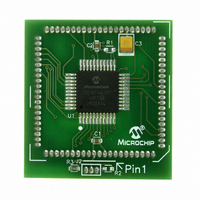
MA180023 Microchip Technology, MA180023 Datasheet - Page 143

MA180023
Manufacturer Part Number
MA180023
Description
MODULE PLUG-IN PIC18F46J11 PIM
Manufacturer
Microchip Technology
Series
PIC®r
Datasheet
1.MA180023.pdf
(528 pages)
Specifications of MA180023
Accessory Type
Plug-In Module (PIM) - PIC18F46J11
Tool / Board Applications
General Purpose MCU, MPU, DSP, DSC
Mcu Supported Families
PIC18
Supported Devices
Stand-alone Or W/ HPC(DM183022) Or PIC18(DM183032)
Silicon Manufacturer
Microchip
Core Architecture
PIC
Core Sub-architecture
PIC18
Silicon Core Number
PIC18F
Silicon Family Name
PIC18FxxJxx
Lead Free Status / RoHS Status
Lead free / RoHS Compliant
For Use With/related Products
HPC Explorer Board (DM183022) or PIC18 Explorer Board (DM183032)
For Use With
DM183032 - BOARD EXPLORER PICDEM PIC18DM183022 - BOARD DEMO PIC18FXX22 64/80TQFP
Lead Free Status / RoHS Status
Lead free / RoHS Compliant
Available stocks
Company
Part Number
Manufacturer
Quantity
Price
Company:
Part Number:
MA180023
Manufacturer:
Microchip Technology
Quantity:
135
- Current page: 143 of 528
- Download datasheet (8Mb)
TABLE 9-11:
TABLE 9-12:
© 2009 Microchip Technology Inc.
PORTE
LATE
TRISE
ANCON0
Legend: — = unimplemented, read as ‘0’. Shaded cells are not used by PORTE.
Note 1:
RE0/AN5/
PMRD
RE1/AN6/
PMWR
RE2/AN7/
PMCS
V
V
AV
V
V
V
AV
AV
Legend: DIG = Digital level output; TTL = TTL input buffer; ST = Schmitt Trigger input buffer; ANA = Analog level
SS
SS
DD
DD
DDCORE
Note 1: PORTD Pull-up Enable bit
Name
SS
DD
DD
1
2
1
2
(1)
1
1
2
2:
Pin
(1)
(1)
2: PORTE Pull-up Enable bit
/V
These registers are not available in 28-pin devices.
These bits are only available in 44-pin devices.
I = Input; O = Output; P = Power
CAP
0 = All PORTD pull-ups are disabled
1 = PORTD pull-ups are enabled for any input pad
0 = All PORTE pull-ups are disabled
1 = PORTE pull-ups are enabled for any input pad
PCFG7
RDPU
Bit 7
—
—
PORTE I/O SUMMARY
SUMMARY OF REGISTERS ASSOCIATED WITH PORTE
Function
V
PMWR
PMRD
PMCS
DDCORE
(3)
V
(2)
RE0
AN5
RE1
AN6
RE2
AN7
—
—
—
—
CAP
PCFG6
REPU
Bit 6
—
—
Setting
TRIS
(4)
—
—
—
—
—
—
(2)
1
0
1
1
0
1
0
1
1
0
1
0
1
0
PCFG5
Bit 5
I/O
—
—
—
—
O
O
O
O
O
O
P
P
P
P
P
P
I
I
I
I
I
I
I
I
(2)
ST/TTL Parallel Master Port io_rd_in.
ST/TTL Parallel Master Port io_wr_in.
Type
ANA
ANA
ANA
DIG
DIG
DIG
DIG
DIG
DIG
I/O
ST
ST
ST
—
—
—
—
—
—
PCFG4
Bit 4
—
—
—
PORTE<0> data input; disabled when analog input enabled.
LATE<0> data output; not affected by analog input.
A/D input channel 5; default input configuration on POR.
Parallel Master Port read strobe.
PORTE<1> data input; disabled when analog input enabled.
LATE<1> data output; not affected by analog input.
A/D input channel 6; default input configuration on POR.
Parallel Master Port write strobe.
PORTE<2> data input; disabled when analog input enabled.
LATE<2> data output; not affected by analog input.
A/D input channel 7; default input configuration on POR.
Parallel Master Port byte enable.
Ground reference for logic and I/O pins.
Ground reference for analog modules.
Positive supply for peripheral digital logic and I/O pins.
Positive supply for microcontroller core logic (regulator disabled).
External filter capacitor connection (regulator enabled).
Positive supply for analog modules.
PIC18F46J11 FAMILY
PCFG3
Bit 3
—
—
—
TRISE2
PCFG2
LATE2
Bit 2
RE2
Description
TRISE1
PCFG1
LATE1
Bit 1
RE1
TRISE0
PCFG0
LATE0
Bit 0
DS39932C-page 143
RE0
on page
Values
Reset
86
86
85
87
Related parts for MA180023
Image
Part Number
Description
Manufacturer
Datasheet
Request
R

Part Number:
Description:
Manufacturer:
Microchip Technology Inc.
Datasheet:

Part Number:
Description:
Manufacturer:
Microchip Technology Inc.
Datasheet:

Part Number:
Description:
Manufacturer:
Microchip Technology Inc.
Datasheet:

Part Number:
Description:
Manufacturer:
Microchip Technology Inc.
Datasheet:

Part Number:
Description:
Manufacturer:
Microchip Technology Inc.
Datasheet:

Part Number:
Description:
Manufacturer:
Microchip Technology Inc.
Datasheet:

Part Number:
Description:
Manufacturer:
Microchip Technology Inc.
Datasheet:

Part Number:
Description:
Manufacturer:
Microchip Technology Inc.
Datasheet:


