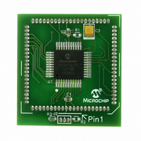
MA180023 Microchip Technology, MA180023 Datasheet - Page 175

MA180023
Manufacturer Part Number
MA180023
Description
MODULE PLUG-IN PIC18F46J11 PIM
Manufacturer
Microchip Technology
Series
PIC®r
Datasheet
1.MA180023.pdf
(528 pages)
Specifications of MA180023
Accessory Type
Plug-In Module (PIM) - PIC18F46J11
Tool / Board Applications
General Purpose MCU, MPU, DSP, DSC
Mcu Supported Families
PIC18
Supported Devices
Stand-alone Or W/ HPC(DM183022) Or PIC18(DM183032)
Silicon Manufacturer
Microchip
Core Architecture
PIC
Core Sub-architecture
PIC18
Silicon Core Number
PIC18F
Silicon Family Name
PIC18FxxJxx
Lead Free Status / RoHS Status
Lead free / RoHS Compliant
For Use With/related Products
HPC Explorer Board (DM183022) or PIC18 Explorer Board (DM183032)
For Use With
DM183032 - BOARD EXPLORER PICDEM PIC18DM183022 - BOARD DEMO PIC18FXX22 64/80TQFP
Lead Free Status / RoHS Status
Lead free / RoHS Compliant
Available stocks
Company
Part Number
Manufacturer
Quantity
Price
Company:
Part Number:
MA180023
Manufacturer:
Microchip Technology
Quantity:
135
- Current page: 175 of 528
- Download datasheet (8Mb)
10.2.2
When chip select is active and a write strobe occurs
(PMCS = 1 and PMWR = 1), the data from PMD<7:0>
is captured into the lower PMDIN1L register. The
PMPIF and IBF flag bits are set when the write
ends.The timing for the control signals in Write mode is
displayed in Figure 10-3. The polarity of the control
signals are configurable.
FIGURE 10-3:
FIGURE 10-4:
© 2009 Microchip Technology Inc.
PMD<7:0>
PMD<7:0>
PMCS1
PMCS1
PMWR
PMWR
PMPIF
PMPIF
PMRD
PMRD
OBE
OBE
IBF
IBF
WRITE TO SLAVE PORT
PARALLEL SLAVE PORT WRITE WAVEFORMS
PARALLEL SLAVE PORT READ WAVEFORMS
PIC18F46J11 FAMILY
10.2.3
When chip select is active and a read strobe occurs
(PMCS = 1 and PMRD = 1), the data from the
PMDOUT1L register (PMDOUT1L<7:0>) is presented
onto PMD<7:0>. Figure 10-4 provides the timing for the
control signals in Read mode.
|
|
READ FROM SLAVE PORT
Q4
Q4
|
|
Q1
Q1
|
|
Q2
Q2
|
|
DS39932C-page 175
Q3
Q3
|
|
Q4
Q4
Related parts for MA180023
Image
Part Number
Description
Manufacturer
Datasheet
Request
R

Part Number:
Description:
Manufacturer:
Microchip Technology Inc.
Datasheet:

Part Number:
Description:
Manufacturer:
Microchip Technology Inc.
Datasheet:

Part Number:
Description:
Manufacturer:
Microchip Technology Inc.
Datasheet:

Part Number:
Description:
Manufacturer:
Microchip Technology Inc.
Datasheet:

Part Number:
Description:
Manufacturer:
Microchip Technology Inc.
Datasheet:

Part Number:
Description:
Manufacturer:
Microchip Technology Inc.
Datasheet:

Part Number:
Description:
Manufacturer:
Microchip Technology Inc.
Datasheet:

Part Number:
Description:
Manufacturer:
Microchip Technology Inc.
Datasheet:


