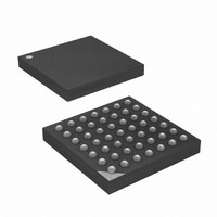
ATXMEGA32A4-CUR Atmel, ATXMEGA32A4-CUR Datasheet - Page 303

ATXMEGA32A4-CUR
Manufacturer Part Number
ATXMEGA32A4-CUR
Description
MCU AVR 32+4 FLASH 49VFBGA
Manufacturer
Atmel
Series
AVR® XMEGAr
Specifications of ATXMEGA32A4-CUR
Core Processor
AVR
Core Size
8/16-Bit
Speed
32MHz
Connectivity
I²C, IrDA, SPI, UART/USART
Peripherals
Brown-out Detect/Reset, DMA, POR, PWM, WDT
Number Of I /o
34
Program Memory Size
32KB (16K x 16)
Program Memory Type
FLASH
Eeprom Size
2K x 8
Ram Size
4K x 8
Voltage - Supply (vcc/vdd)
1.6 V ~ 3.6 V
Data Converters
A/D 12x12b, D/A 2x12b
Oscillator Type
Internal
Operating Temperature
-40°C ~ 85°C
Package / Case
49-VFBGA
For Use With
ATAVRONEKIT - KIT AVR/AVR32 DEBUGGER/PROGRMMRATSTK600 - DEV KIT FOR AVR/AVR32770-1007 - ISP 4PORT ATMEL AVR MCU SPI/JTAG770-1004 - ISP 4PORT FOR ATMEL AVR MCU SPI
Lead Free Status / RoHS Status
Lead free / RoHS Compliant
Available stocks
Company
Part Number
Manufacturer
Quantity
Price
- Current page: 303 of 445
- Download datasheet (6Mb)
25.16.3
8077H–AVR–12/09
REFCTRL - ADC Reference Control register
• Bit 4 - CONVMODE: ADC Conversion Mode
This bit controls whether the ADC should work in signed or unsigned mode. By default this bit is
zero and the ADC is then configured for unsigned mode where single ended and internal signals
can be measured. When this bit is set to one the ADC is configured for signed mode where also
differential input can be used.
• Bit 3 - FREERUN: ADC Free Running Mode
This bit controls the free running mode for the ADC. When the bit is set to one the ADC channels
defined in the EVCTRL register are swept repeatedly.
• Bits 2:1 - RESOLUTION[1:0]: ADC Conversion Result Resolution
These bits define whether the ADC completes the conversion at 12- or 8-bit result. They also
define whether the 12-bit result is left or right oriented in the 16-bit result registers. See
25-2 on page 303
Table 25-2.
• Bit 0 - Reserved
This bit is unused and reserved for future use. For compatibility with future devices, always write
this bit to zero when this register is written.
Note:
• Bit 7:6 – Reserved
These bits are unused and reserved for future use. For compatibility with future devices, always
write these bits to zero when this register is written.
• Bits 6:4 – REFSEL[1:0]: ADC Reference Selection
These bits selects the reference and conversion range for the ADC according to
page
Bit
+0x02
Read/Write
Initial Value
RESOLUTION[1:0]
304.
1. Refer to datasheet for limitations on reference voltage.
00
01
10
11
R
7
0
-
ADC Conversion Result resolution
for possible settings.
R
6
0
-
Group Configuration
(1)
R/W
LEFT12BIT
5
0
REFSEL[1:0]
12BIT
8BIT
R/W
4
0
R
3
0
-
Description
12-bit result, right adjusted
Reserved
8-bit result, right adjusted
12-bit result, left adjusted
R
2
0
-
BANDGAP
R/W
1
0
XMEGA A
TEMPREF
R/W
0
0
Table 25-3 on
REFCTRL
Table
303
Related parts for ATXMEGA32A4-CUR
Image
Part Number
Description
Manufacturer
Datasheet
Request
R

Part Number:
Description:
DEV KIT FOR AVR/AVR32
Manufacturer:
Atmel
Datasheet:

Part Number:
Description:
INTERVAL AND WIPE/WASH WIPER CONTROL IC WITH DELAY
Manufacturer:
ATMEL Corporation
Datasheet:

Part Number:
Description:
Low-Voltage Voice-Switched IC for Hands-Free Operation
Manufacturer:
ATMEL Corporation
Datasheet:

Part Number:
Description:
MONOLITHIC INTEGRATED FEATUREPHONE CIRCUIT
Manufacturer:
ATMEL Corporation
Datasheet:

Part Number:
Description:
AM-FM Receiver IC U4255BM-M
Manufacturer:
ATMEL Corporation
Datasheet:

Part Number:
Description:
Monolithic Integrated Feature Phone Circuit
Manufacturer:
ATMEL Corporation
Datasheet:

Part Number:
Description:
Multistandard Video-IF and Quasi Parallel Sound Processing
Manufacturer:
ATMEL Corporation
Datasheet:

Part Number:
Description:
High-performance EE PLD
Manufacturer:
ATMEL Corporation
Datasheet:

Part Number:
Description:
8-bit Flash Microcontroller
Manufacturer:
ATMEL Corporation
Datasheet:

Part Number:
Description:
2-Wire Serial EEPROM
Manufacturer:
ATMEL Corporation
Datasheet:


