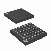
ATXMEGA32A4-CUR Atmel, ATXMEGA32A4-CUR Datasheet - Page 235

ATXMEGA32A4-CUR
Manufacturer Part Number
ATXMEGA32A4-CUR
Description
MCU AVR 32+4 FLASH 49VFBGA
Manufacturer
Atmel
Series
AVR® XMEGAr
Specifications of ATXMEGA32A4-CUR
Core Processor
AVR
Core Size
8/16-Bit
Speed
32MHz
Connectivity
I²C, IrDA, SPI, UART/USART
Peripherals
Brown-out Detect/Reset, DMA, POR, PWM, WDT
Number Of I /o
34
Program Memory Size
32KB (16K x 16)
Program Memory Type
FLASH
Eeprom Size
2K x 8
Ram Size
4K x 8
Voltage - Supply (vcc/vdd)
1.6 V ~ 3.6 V
Data Converters
A/D 12x12b, D/A 2x12b
Oscillator Type
Internal
Operating Temperature
-40°C ~ 85°C
Package / Case
49-VFBGA
For Use With
ATAVRONEKIT - KIT AVR/AVR32 DEBUGGER/PROGRMMRATSTK600 - DEV KIT FOR AVR/AVR32770-1007 - ISP 4PORT ATMEL AVR MCU SPI/JTAG770-1004 - ISP 4PORT FOR ATMEL AVR MCU SPI
Lead Free Status / RoHS Status
Lead free / RoHS Compliant
Available stocks
Company
Part Number
Manufacturer
Quantity
Price
- Current page: 235 of 445
- Download datasheet (6Mb)
21. USART
21.1
21.2
8077H–AVR–12/09
Features
Overview
•
•
•
•
•
•
•
•
•
•
•
•
•
The Universal Synchronous and Asynchronous serial Receiver and Transmitter (USART) is a
highly flexible serial communication module. The USART supports full duplex communication,
and both asynchronous and clocked synchronous operation. The USART can be set in Master
SPI compliant mode and be used for SPI communication.
Communication is frame based, and the frame format can be customized to support a wide
range of standards. The USART is buffered in both direction, enabling continued data transmis-
sion without any delay between frames. There are separate interrupt vectors for receive and
transmit complete, enabling fully interrupt driven communication. Frame error and buffer over-
flow are detected in hardware and indicated with separate status flags. Even or odd parity
generation and parity check can also be enabled.
A block diagram of the USART is shown in
Clock Generator, the Transmitter and the Receiver, indicated in dashed boxes.
Full Duplex Operation (Independent Serial Receive and Transmit Registers)
Asynchronous or Synchronous Operation
Master or Slave Clocked Synchronous Operation
Enhanced Baud Rate Generator
Supports Serial Frames with 5, 6, 7, 8, or 9 Data Bits and 1 or 2 Stop Bits
Odd or Even Parity Generation and Parity Check Supported by Hardware
Data OverRun and Framing Error Detection
Noise Filtering Includes False Start Bit Detection and Digital Low Pass Filter
Separate Interrupts on TX Complete, TX Data Register Empty and RX Complete
Multi-processor Communication Mode
Double Speed Asynchronous Communication Mode
Master SPI mode, Three-wire Synchronous Data Transfer
IRCOM Module for IrDA compliant pulse modulation/demodulation
– Supports all four SPI Modes of Operation (Mode 0, 1, 2, and 3)
– LSB First or MSB First Data Transfer (Configurable Data Order)
– Queued Operation (Double Buffered)
– High Speed Operation (f
XCK,max
= f
PER
/2)
Figure 21-1 on page
236. The main parts are the
XMEGA A
235
Related parts for ATXMEGA32A4-CUR
Image
Part Number
Description
Manufacturer
Datasheet
Request
R

Part Number:
Description:
DEV KIT FOR AVR/AVR32
Manufacturer:
Atmel
Datasheet:

Part Number:
Description:
INTERVAL AND WIPE/WASH WIPER CONTROL IC WITH DELAY
Manufacturer:
ATMEL Corporation
Datasheet:

Part Number:
Description:
Low-Voltage Voice-Switched IC for Hands-Free Operation
Manufacturer:
ATMEL Corporation
Datasheet:

Part Number:
Description:
MONOLITHIC INTEGRATED FEATUREPHONE CIRCUIT
Manufacturer:
ATMEL Corporation
Datasheet:

Part Number:
Description:
AM-FM Receiver IC U4255BM-M
Manufacturer:
ATMEL Corporation
Datasheet:

Part Number:
Description:
Monolithic Integrated Feature Phone Circuit
Manufacturer:
ATMEL Corporation
Datasheet:

Part Number:
Description:
Multistandard Video-IF and Quasi Parallel Sound Processing
Manufacturer:
ATMEL Corporation
Datasheet:

Part Number:
Description:
High-performance EE PLD
Manufacturer:
ATMEL Corporation
Datasheet:

Part Number:
Description:
8-bit Flash Microcontroller
Manufacturer:
ATMEL Corporation
Datasheet:

Part Number:
Description:
2-Wire Serial EEPROM
Manufacturer:
ATMEL Corporation
Datasheet:


