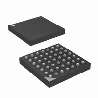
ATXMEGA32A4-CUR Atmel, ATXMEGA32A4-CUR Datasheet - Page 125

ATXMEGA32A4-CUR
Manufacturer Part Number
ATXMEGA32A4-CUR
Description
MCU AVR 32+4 FLASH 49VFBGA
Manufacturer
Atmel
Series
AVR® XMEGAr
Specifications of ATXMEGA32A4-CUR
Core Processor
AVR
Core Size
8/16-Bit
Speed
32MHz
Connectivity
I²C, IrDA, SPI, UART/USART
Peripherals
Brown-out Detect/Reset, DMA, POR, PWM, WDT
Number Of I /o
34
Program Memory Size
32KB (16K x 16)
Program Memory Type
FLASH
Eeprom Size
2K x 8
Ram Size
4K x 8
Voltage - Supply (vcc/vdd)
1.6 V ~ 3.6 V
Data Converters
A/D 12x12b, D/A 2x12b
Oscillator Type
Internal
Operating Temperature
-40°C ~ 85°C
Package / Case
49-VFBGA
For Use With
ATAVRONEKIT - KIT AVR/AVR32 DEBUGGER/PROGRMMRATSTK600 - DEV KIT FOR AVR/AVR32770-1007 - ISP 4PORT ATMEL AVR MCU SPI/JTAG770-1004 - ISP 4PORT FOR ATMEL AVR MCU SPI
Lead Free Status / RoHS Status
Lead free / RoHS Compliant
Available stocks
Company
Part Number
Manufacturer
Quantity
Price
- Current page: 125 of 445
- Download datasheet (6Mb)
12.5
12.6
12.6.1
8077H–AVR–12/09
Interrupt level
Interrupt priority
Static priority
rupt execution response time is increased by five clock cycles. In addition the response time is
increased by the start-up time from the selected sleep mode.
A return from an interrupt handling routine takes five clock cycles. During these five clock cycles,
the program counter is popped from the stack and the stack pointer is incremented.
The interrupt level is independently selected for each interrupt source. For any interrupt request,
the PMIC also receives the interrupt level for the interrupt. The interrupt levels and their corre-
sponding bit values for the interrupt level configuration of all interrupts is shown in
Table 12-1.
The interrupt level of an interrupt request is compared against the current level and status of the
interrupt controller. An interrupt request on higher level will interrupt any ongoing interrupt han-
dler from a lower level interrupt. When returning from the higher level interrupt handler, the
execution of the lower level interrupt handler will continue.
Within each interrupt level, all interrupts have a priority. When several interrupt requests are
pending, the order of which interrupts are acknowledged is decided both by the level and the pri-
ority of the interrupt request. Interrupts can be organized in a static or dynamic (round-robin)
priority scheme. High and Medium level interrupts and the NMI will always have static priority.
For Low level interrupts, static or dynamic priority scheduling can be selected.
Interrupt vectors (IVEC) are located at fixed addresses. For static priority, the interrupt vector
address decides the priority within one interrupt level where the lowest interrupt vector address
has the highest priority. Refer to the device data sheet for interrupt vector table with the base
address for all modules and peripherals with interrupt. Refer to the interrupt vector summary of
each module and peripheral in this manual for a list of interrupts and their corresponding offset
address within the different modules and peripherals.
Interrupt level
configuration
00
01
10
11
Interrupt level
Group Configuration
MED
OFF
LO
HI
Description
Interrupt disabled.
Low level interrupt
Medium level interrupt
High level interrupt
XMEGA A
Table
12-1.
125
Related parts for ATXMEGA32A4-CUR
Image
Part Number
Description
Manufacturer
Datasheet
Request
R

Part Number:
Description:
DEV KIT FOR AVR/AVR32
Manufacturer:
Atmel
Datasheet:

Part Number:
Description:
INTERVAL AND WIPE/WASH WIPER CONTROL IC WITH DELAY
Manufacturer:
ATMEL Corporation
Datasheet:

Part Number:
Description:
Low-Voltage Voice-Switched IC for Hands-Free Operation
Manufacturer:
ATMEL Corporation
Datasheet:

Part Number:
Description:
MONOLITHIC INTEGRATED FEATUREPHONE CIRCUIT
Manufacturer:
ATMEL Corporation
Datasheet:

Part Number:
Description:
AM-FM Receiver IC U4255BM-M
Manufacturer:
ATMEL Corporation
Datasheet:

Part Number:
Description:
Monolithic Integrated Feature Phone Circuit
Manufacturer:
ATMEL Corporation
Datasheet:

Part Number:
Description:
Multistandard Video-IF and Quasi Parallel Sound Processing
Manufacturer:
ATMEL Corporation
Datasheet:

Part Number:
Description:
High-performance EE PLD
Manufacturer:
ATMEL Corporation
Datasheet:

Part Number:
Description:
8-bit Flash Microcontroller
Manufacturer:
ATMEL Corporation
Datasheet:

Part Number:
Description:
2-Wire Serial EEPROM
Manufacturer:
ATMEL Corporation
Datasheet:


