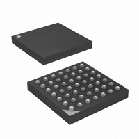
ATXMEGA32A4-CUR Atmel, ATXMEGA32A4-CUR Datasheet - Page 20

ATXMEGA32A4-CUR
Manufacturer Part Number
ATXMEGA32A4-CUR
Description
MCU AVR 32+4 FLASH 49VFBGA
Manufacturer
Atmel
Series
AVR® XMEGAr
Specifications of ATXMEGA32A4-CUR
Core Processor
AVR
Core Size
8/16-Bit
Speed
32MHz
Connectivity
I²C, IrDA, SPI, UART/USART
Peripherals
Brown-out Detect/Reset, DMA, POR, PWM, WDT
Number Of I /o
34
Program Memory Size
32KB (16K x 16)
Program Memory Type
FLASH
Eeprom Size
2K x 8
Ram Size
4K x 8
Voltage - Supply (vcc/vdd)
1.6 V ~ 3.6 V
Data Converters
A/D 12x12b, D/A 2x12b
Oscillator Type
Internal
Operating Temperature
-40°C ~ 85°C
Package / Case
49-VFBGA
For Use With
ATAVRONEKIT - KIT AVR/AVR32 DEBUGGER/PROGRMMRATSTK600 - DEV KIT FOR AVR/AVR32770-1007 - ISP 4PORT ATMEL AVR MCU SPI/JTAG770-1004 - ISP 4PORT FOR ATMEL AVR MCU SPI
Lead Free Status / RoHS Status
Lead free / RoHS Compliant
Available stocks
Company
Part Number
Manufacturer
Quantity
Price
- Current page: 20 of 445
- Download datasheet (6Mb)
4.3.1
4.3.2
4.3.3
4.3.4
4.3.5
4.4
8077H–AVR–12/09
Fuses and Lockbits
Application Section
Application Table section
Boot Loader Section
Production Signature Row
User Signature Row
The Application section is the section of the Flash that is used for storing the executable applica-
tion code. The protection level for the Application section can be selected by the Boot Lock Bits
for this section. The Application section can not store any Boot Loader code since the SPM
instruction cannot be executed from the Application section.
The Application Table section is a part of the Application Section of the Flash that can be used
for storing data. The size is identical to the Boot Loader Section. The protection level for the
Application Table section can be selected by the Boot Lock Bits for this section. The possibilities
for different protection levels on the Application Section and the Application Table Section
enable safe parameter storage in the Program Memory. If this section is not used for data, appli-
cation code can be reside here.
While the Application Section is used for storing the application code, the Boot Loader software
must be located in the Boot Loader Section since the SPM instruction only can initiate program-
ming when executing from the this section. The SPM instruction can access the entire Flash,
including the Boot Loader Section itself. The protection level for the Boot Loader Section can be
selected by the Boot Loader Lock bits. If this section is not used for Boot Loader software, appli-
cation code can be stored here.
The Production Signature Row is a separate memory section for factory programmed data. It
contains calibration data for functions such as oscillators and analog modules. Some of the cali-
bration values will be automatically loaded to the corresponding module or peripheral unit during
reset. Other values must be loaded from the signature row and written to the corresponding
peripheral registers from software. For details on the calibration conditions such as temperature,
voltage references etc. refer to device data sheet.
The production signature row also contains a device ID that identify each microcontroller device
type, and a serial number that is unique for each manufactured device. The serial number con-
sist of the production LOT number, wafer number, and wafer coordinates for the device.
The production signature row can not be written or erased, but it can be read from both applica-
tion software and external programming.
The User Signature Row is a separate memory section that is fully accessible (read and write)
from application software and external programming. The user signature row is one flash page
in size, and is meant for static user parameter storage, such as calibration data, custom serial
numbers or identification numbers, random number seeds etc. This section is not erased by
Chip Erase commands that erase the Flash, and requires a dedicated erase command. This
ensures parameter storage during multiple program/erase session and on-chip debug sessions.
The Fuses are used to set important system function and can only be written from an external
programming interface. The application software can read the fuses. The fuses are used to con-
figure reset sources such as Brown-out Detector and Watchdog, Start-up configuration, JTAG
enable and JTAG user ID.
XMEGA A
20
Related parts for ATXMEGA32A4-CUR
Image
Part Number
Description
Manufacturer
Datasheet
Request
R

Part Number:
Description:
DEV KIT FOR AVR/AVR32
Manufacturer:
Atmel
Datasheet:

Part Number:
Description:
INTERVAL AND WIPE/WASH WIPER CONTROL IC WITH DELAY
Manufacturer:
ATMEL Corporation
Datasheet:

Part Number:
Description:
Low-Voltage Voice-Switched IC for Hands-Free Operation
Manufacturer:
ATMEL Corporation
Datasheet:

Part Number:
Description:
MONOLITHIC INTEGRATED FEATUREPHONE CIRCUIT
Manufacturer:
ATMEL Corporation
Datasheet:

Part Number:
Description:
AM-FM Receiver IC U4255BM-M
Manufacturer:
ATMEL Corporation
Datasheet:

Part Number:
Description:
Monolithic Integrated Feature Phone Circuit
Manufacturer:
ATMEL Corporation
Datasheet:

Part Number:
Description:
Multistandard Video-IF and Quasi Parallel Sound Processing
Manufacturer:
ATMEL Corporation
Datasheet:

Part Number:
Description:
High-performance EE PLD
Manufacturer:
ATMEL Corporation
Datasheet:

Part Number:
Description:
8-bit Flash Microcontroller
Manufacturer:
ATMEL Corporation
Datasheet:

Part Number:
Description:
2-Wire Serial EEPROM
Manufacturer:
ATMEL Corporation
Datasheet:


