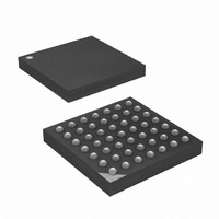
ATXMEGA32A4-CUR Atmel, ATXMEGA32A4-CUR Datasheet - Page 238

ATXMEGA32A4-CUR
Manufacturer Part Number
ATXMEGA32A4-CUR
Description
MCU AVR 32+4 FLASH 49VFBGA
Manufacturer
Atmel
Series
AVR® XMEGAr
Specifications of ATXMEGA32A4-CUR
Core Processor
AVR
Core Size
8/16-Bit
Speed
32MHz
Connectivity
I²C, IrDA, SPI, UART/USART
Peripherals
Brown-out Detect/Reset, DMA, POR, PWM, WDT
Number Of I /o
34
Program Memory Size
32KB (16K x 16)
Program Memory Type
FLASH
Eeprom Size
2K x 8
Ram Size
4K x 8
Voltage - Supply (vcc/vdd)
1.6 V ~ 3.6 V
Data Converters
A/D 12x12b, D/A 2x12b
Oscillator Type
Internal
Operating Temperature
-40°C ~ 85°C
Package / Case
49-VFBGA
For Use With
ATAVRONEKIT - KIT AVR/AVR32 DEBUGGER/PROGRMMRATSTK600 - DEV KIT FOR AVR/AVR32770-1007 - ISP 4PORT ATMEL AVR MCU SPI/JTAG770-1004 - ISP 4PORT FOR ATMEL AVR MCU SPI
Lead Free Status / RoHS Status
Lead free / RoHS Compliant
Available stocks
Company
Part Number
Manufacturer
Quantity
Price
- Current page: 238 of 445
- Download datasheet (6Mb)
Table 21-1.
Note:
21.3.2
21.3.3
8077H–AVR–12/09
Operating Mode
Asynchronous Normal
Speed mode (CLK2X = 0)
Asynchronous Double
Speed mode (CLK2X = 1)
Synchronous and SPI
Master mode
1. The baud rate is defined to be the transfer rate in bit per second (bps)
External Clock
Double Speed Operation (CLK2X)
Equations for Calculating Baud Rate Register Setting
External clock is used in synchronous slave mode operation. The XCK clock input is sampled on
the Peripheral Clock frequency (f
meta-stability. The output from the synchronization register is then passed through an edge
detector. This process introduces a delay of two peripheral clock periods, and therefore the max-
imum external XCK clock frequency (f
Each high and low period the XCK clock cycles must be sampled twice by the Peripheral Clock.
If the XCK clock has jitter, or the high/low period duty cycle is not 50/50, the maximum XCK
clock speed must be reduced accordingly.
Double Speed operation can be enabled to allow for higher baud rates on lower peripheral clock
frequencies under asynchronous operation. When Double Speed operation is enabled the baud
rate for a given asynchronous baud rate setting as shown in
bled. In this mode the Receiver will use half the number of samples (reduced from 16 to 8) for
data sampling and clock recovery. Due to the reduced sampling more accurate baud rate setting
and peripheral clock are required. See
243
f
XCK
Conditions
BSCALE ≥ 0
BSCALE < 0
BSCALE ≥ 0
BSCALE < 0
f
f
f
f
f
BAUD
BAUD
BAUD
BAUD
BAUD
for more details on accuracy.
<
f
---------- -
PER
4
≤
≤
≤
≤
<
f
---------- -
f
---------- -
f
---------- -
f
---------- -
f
---------- -
PER
PER
PER
PER
PER
16
16
8
8
2
f
f
BAUD
BAUD
f
f
BAUD
BAUD
Equation for Calculation
PER
=
=
f
=
BAUD
=
------------------------------------------------------------------ -
16((2
--------------------------------------------------------------- -
8((2
) by a synchronization register to minimize the chance of
XCK
Baud Rate
-------------------------------------------------------------- -
2
------------------------------------------------------------- -
2
BSCALE
BSCALE
Section 21.8 ”Asynchronous Data Reception” on page
BSCALE
)is limited by the following equation:
=
BSCALE
------------------------------------ -
2
⋅
⋅
f
(
⋅
f
PER
f
8
BSEL
f
PER
16(
PER
⋅
PER
(1)
f
⋅
⋅
PER
BSEL )
(
BSEL )
BSEL
BSEL
+
1
+
)
+
+
+
1)
1
1)
1)
)
Table 21-1 on page 238
BSEL
BSEL
BSEL
BSEL
Equation for Calculation
BSEL
=
=
=
=
---------------------
2
------------------------------------------------ 1
2
BSEL Value
---------------------
2
-------------------------------------------- - 1
2
BSCALE
BSCALE
BSCALE
BSCALE
1
=
1
XMEGA A
------------------ - 1
2f
f
f
f
BAUD
PER
PER
PER
⎛
⎝
⋅
⎛
⎝
--------------------- - 1
16f
⋅ f
16
------------------ - 1
8f
8
f
f
BAUD
PER
PER
f
BAUD
BAUD
will be dou-
BAUD
–
–
–
–
–
⎞
⎠
⎞
⎠
238
Related parts for ATXMEGA32A4-CUR
Image
Part Number
Description
Manufacturer
Datasheet
Request
R

Part Number:
Description:
DEV KIT FOR AVR/AVR32
Manufacturer:
Atmel
Datasheet:

Part Number:
Description:
INTERVAL AND WIPE/WASH WIPER CONTROL IC WITH DELAY
Manufacturer:
ATMEL Corporation
Datasheet:

Part Number:
Description:
Low-Voltage Voice-Switched IC for Hands-Free Operation
Manufacturer:
ATMEL Corporation
Datasheet:

Part Number:
Description:
MONOLITHIC INTEGRATED FEATUREPHONE CIRCUIT
Manufacturer:
ATMEL Corporation
Datasheet:

Part Number:
Description:
AM-FM Receiver IC U4255BM-M
Manufacturer:
ATMEL Corporation
Datasheet:

Part Number:
Description:
Monolithic Integrated Feature Phone Circuit
Manufacturer:
ATMEL Corporation
Datasheet:

Part Number:
Description:
Multistandard Video-IF and Quasi Parallel Sound Processing
Manufacturer:
ATMEL Corporation
Datasheet:

Part Number:
Description:
High-performance EE PLD
Manufacturer:
ATMEL Corporation
Datasheet:

Part Number:
Description:
8-bit Flash Microcontroller
Manufacturer:
ATMEL Corporation
Datasheet:

Part Number:
Description:
2-Wire Serial EEPROM
Manufacturer:
ATMEL Corporation
Datasheet:


