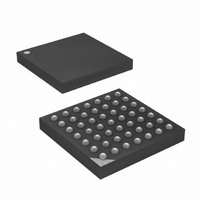
ATXMEGA32A4-CUR Atmel, ATXMEGA32A4-CUR Datasheet - Page 179

ATXMEGA32A4-CUR
Manufacturer Part Number
ATXMEGA32A4-CUR
Description
MCU AVR 32+4 FLASH 49VFBGA
Manufacturer
Atmel
Series
AVR® XMEGAr
Specifications of ATXMEGA32A4-CUR
Core Processor
AVR
Core Size
8/16-Bit
Speed
32MHz
Connectivity
I²C, IrDA, SPI, UART/USART
Peripherals
Brown-out Detect/Reset, DMA, POR, PWM, WDT
Number Of I /o
34
Program Memory Size
32KB (16K x 16)
Program Memory Type
FLASH
Eeprom Size
2K x 8
Ram Size
4K x 8
Voltage - Supply (vcc/vdd)
1.6 V ~ 3.6 V
Data Converters
A/D 12x12b, D/A 2x12b
Oscillator Type
Internal
Operating Temperature
-40°C ~ 85°C
Package / Case
49-VFBGA
For Use With
ATAVRONEKIT - KIT AVR/AVR32 DEBUGGER/PROGRMMRATSTK600 - DEV KIT FOR AVR/AVR32770-1007 - ISP 4PORT ATMEL AVR MCU SPI/JTAG770-1004 - ISP 4PORT FOR ATMEL AVR MCU SPI
Lead Free Status / RoHS Status
Lead free / RoHS Compliant
Available stocks
Company
Part Number
Manufacturer
Quantity
Price
- Current page: 179 of 445
- Download datasheet (6Mb)
15.4
8077H–AVR–12/09
Dead Time Insertion
The Dead Time Insertion (DTI) unit enables generation of “off” time where both the non-inverted
Low Side (LS) and inverted High Side (HS) of the WG output is low. This “off” time is called
dead-time, and dead-time insertion ensure that the LS and HS does not switch simultaneously.
The DTI unit consists of four equal dead time generators, one for each of the capture or com-
pare channel in Timer/Counter 0.
time generator. The dead time registers that define the number of peripheral clock cycles the
dead time is going to last, are common for all four channels. The High Side and Low Side can
have independent dead time setting and the dead time registers are double buffered.
Figure 15-3. Dead Time Generator block diagram
As shown in
one for each peripheral clock cycle until it reaches zero. A non-zero counter value will force both
the Low Side and High Side outputs into their “off” state. When a change is detected on the WG
output, the Dead Time Counter is reloaded with the DTx register value according to the edge of
the input. Positive edge initiates a counter reload of the DTLS Register and a negative edge a
reload of DTHS Register.
WG output
Dead Time Generator
Figure 15-4 on page
D
Q
Edge Detect
V
Figure 15-3 on page 179
180, the 8-bit Dead Time Counter (dti_cnt) is decremented by
DTLSBUF
DTILS
LOAD
E
V
shows the block diagram of one dead
Counter ("dti_cnt")
DTHSBUF
= 0
DTIHS
XMEGA A
"dtls"
(To PORT)
"dths"
(To PORT)
179
Related parts for ATXMEGA32A4-CUR
Image
Part Number
Description
Manufacturer
Datasheet
Request
R

Part Number:
Description:
DEV KIT FOR AVR/AVR32
Manufacturer:
Atmel
Datasheet:

Part Number:
Description:
INTERVAL AND WIPE/WASH WIPER CONTROL IC WITH DELAY
Manufacturer:
ATMEL Corporation
Datasheet:

Part Number:
Description:
Low-Voltage Voice-Switched IC for Hands-Free Operation
Manufacturer:
ATMEL Corporation
Datasheet:

Part Number:
Description:
MONOLITHIC INTEGRATED FEATUREPHONE CIRCUIT
Manufacturer:
ATMEL Corporation
Datasheet:

Part Number:
Description:
AM-FM Receiver IC U4255BM-M
Manufacturer:
ATMEL Corporation
Datasheet:

Part Number:
Description:
Monolithic Integrated Feature Phone Circuit
Manufacturer:
ATMEL Corporation
Datasheet:

Part Number:
Description:
Multistandard Video-IF and Quasi Parallel Sound Processing
Manufacturer:
ATMEL Corporation
Datasheet:

Part Number:
Description:
High-performance EE PLD
Manufacturer:
ATMEL Corporation
Datasheet:

Part Number:
Description:
8-bit Flash Microcontroller
Manufacturer:
ATMEL Corporation
Datasheet:

Part Number:
Description:
2-Wire Serial EEPROM
Manufacturer:
ATMEL Corporation
Datasheet:


