M30290FAHP#U5A Renesas Electronics America, M30290FAHP#U5A Datasheet - Page 333
M30290FAHP#U5A
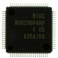
Manufacturer Part Number
M30290FAHP#U5A
Description
IC M16C/29 MCU FLASH 96K 80LQFP
Manufacturer
Renesas Electronics America
Series
M16C™ M16C/Tiny/29r
Datasheet
1.M30291FCHPU5A.pdf
(501 pages)
Specifications of M30290FAHP#U5A
Core Processor
M16C/60
Core Size
16-Bit
Speed
20MHz
Connectivity
CAN, I²C, IEBus, SIO, UART/USART
Peripherals
DMA, POR, PWM, Voltage Detect, WDT
Number Of I /o
71
Program Memory Size
96KB (96K x 8)
Program Memory Type
FLASH
Ram Size
8K x 8
Voltage - Supply (vcc/vdd)
2.7 V ~ 5.5 V
Data Converters
A/D 27x10b
Oscillator Type
Internal
Operating Temperature
-20°C ~ 85°C
Package / Case
80-LQFP
For Use With
R0K330290S000BE - KIT EVAL STARTER FOR M16C/29M30290T2-CPE - EMULATOR COMPACT M16C/26A/28/29M30290T2-CPE-HP - EMULATOR COMPACT FOR M16C/TINY
Lead Free Status / RoHS Status
Lead free / RoHS Compliant
Eeprom Size
-
Available stocks
Company
Part Number
Manufacturer
Quantity
Price

Part Number:
M30290FAHP#U5AM30290FAHP#D3
Manufacturer:
Renesas Electronics America
Quantity:
10 000
Part Number:
M30290FAHP#U5AM30290FAHP#U3A
Manufacturer:
Renesas Electronics America
Quantity:
135
Part Number:
M30290FAHP#U5AM30290FAHP#U3A
Manufacturer:
Renesas Electronics America
Quantity:
10 000


R
R
M
17.6 BasicCAN Mode
e
E
1
. v
J
Figure 17.24 Operation of Slots 14 and 15 in Basic CAN Mode
6
0
When the BasicCAN bit in the C0CTLR register is set to 1 (Basic CAN mode enabled), slots 14 and 15
correspond to Basic CAN mode. During normal operations, individual slots can select either data frame or
remote frame by CPU setting. However, in Basic CAN mode, both frames can be selected.
When slots 14 and 15 are defined as reception slots in Basic CAN mode, received messages are stored in
slots 14 and 15 alternately.
to 15).
When using Basic CAN mode, note the following points.
1
9
C
The received message data format can be determined by the RemActive bit in the C0MCTLj register (j = 0
Figure 17.24 shows the operation of slots 14 and 15 in Basic CAN mode.
1 .
B
(1) Setting of Basic CAN mode has to be done in CAN reset/initialization mode.
(2) Select the same ID for slots 14 and 15. Also, setting of the C0LMAR and C0LMBR register has to be
(3) Define slots 14 and 15 as reception slot only.
(4) There is no protection available against message overwrite. A message can be overwritten by a new
(5) Slots 0 to 13 can be used in the same way as in normal CAN operating mode.
2 /
0
2
9
1
M
the same.
message.
0
G
1
r a
0 -
o r
3 .
1
u
, 0
1
p
2
2
0
0
7
Slot 14
Slot 15
page 307
Locked (empty)
Msg n
f o
Empty
4
5
8
Locked (empty)
Msg n
Msg n+1
Locked
Msg n + 1
(Msg n)
Msg n+2
Msg n+2 (Msg n lost)
Locked (Msg n+1)
Related parts for M30290FAHP#U5A
Image
Part Number
Description
Manufacturer
Datasheet
Request
R

Part Number:
Description:
KIT STARTER FOR M16C/29
Manufacturer:
Renesas Electronics America
Datasheet:

Part Number:
Description:
KIT STARTER FOR R8C/2D
Manufacturer:
Renesas Electronics America
Datasheet:

Part Number:
Description:
R0K33062P STARTER KIT
Manufacturer:
Renesas Electronics America
Datasheet:

Part Number:
Description:
KIT STARTER FOR R8C/23 E8A
Manufacturer:
Renesas Electronics America
Datasheet:

Part Number:
Description:
KIT STARTER FOR R8C/25
Manufacturer:
Renesas Electronics America
Datasheet:

Part Number:
Description:
KIT STARTER H8S2456 SHARPE DSPLY
Manufacturer:
Renesas Electronics America
Datasheet:

Part Number:
Description:
KIT STARTER FOR R8C38C
Manufacturer:
Renesas Electronics America
Datasheet:

Part Number:
Description:
KIT STARTER FOR R8C35C
Manufacturer:
Renesas Electronics America
Datasheet:

Part Number:
Description:
KIT STARTER FOR R8CL3AC+LCD APPS
Manufacturer:
Renesas Electronics America
Datasheet:
Part Number:
Description:
KIT STARTER FOR RX610
Manufacturer:
Renesas Electronics America
Datasheet:

Part Number:
Description:
KIT STARTER FOR R32C/118
Manufacturer:
Renesas Electronics America
Datasheet:

Part Number:
Description:
KIT DEV RSK-R8C/26-29
Manufacturer:
Renesas Electronics America
Datasheet:

Part Number:
Description:
KIT STARTER FOR SH7124
Manufacturer:
Renesas Electronics America
Datasheet:

Part Number:
Description:
KIT STARTER FOR H8SX/1622
Manufacturer:
Renesas Electronics America
Datasheet:

Part Number:
Description:
KIT DEV FOR SH7203
Manufacturer:
Renesas Electronics America
Datasheet: