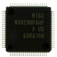
M30290FAHP#U5A Renesas Electronics America, M30290FAHP#U5A Datasheet - Page 143

M30290FAHP#U5A
Manufacturer Part Number
M30290FAHP#U5A
Description
IC M16C/29 MCU FLASH 96K 80LQFP
Manufacturer
Renesas Electronics America
Series
M16C™ M16C/Tiny/29r
Datasheet
1.M30291FCHPU5A.pdf
(501 pages)
Specifications of M30290FAHP#U5A
Core Processor
M16C/60
Core Size
16-Bit
Speed
20MHz
Connectivity
CAN, I²C, IEBus, SIO, UART/USART
Peripherals
DMA, POR, PWM, Voltage Detect, WDT
Number Of I /o
71
Program Memory Size
96KB (96K x 8)
Program Memory Type
FLASH
Ram Size
8K x 8
Voltage - Supply (vcc/vdd)
2.7 V ~ 5.5 V
Data Converters
A/D 27x10b
Oscillator Type
Internal
Operating Temperature
-20°C ~ 85°C
Package / Case
80-LQFP
For Use With
R0K330290S000BE - KIT EVAL STARTER FOR M16C/29M30290T2-CPE - EMULATOR COMPACT M16C/26A/28/29M30290T2-CPE-HP - EMULATOR COMPACT FOR M16C/TINY
Lead Free Status / RoHS Status
Lead free / RoHS Compliant
Eeprom Size
-
Available stocks
Company
Part Number
Manufacturer
Quantity
Price
Part Number:
M30290FAHP#U5AM30290FAHP#D3
Manufacturer:
Renesas Electronics America
Quantity:
10 000
Part Number:
M30290FAHP#U5AM30290FAHP#U3A
Manufacturer:
Renesas Electronics America
Quantity:
135
Part Number:
M30290FAHP#U5AM30290FAHP#U3A
Manufacturer:
Renesas Electronics America
Quantity:
10 000
- Current page: 143 of 501
- Download datasheet (5Mb)
R
R
M
12.2 Timer B
e
E
1
. v
J
Figure 12.15 Timer B Block Diagram
Figure 12.16 TB0MR to TB2MR Registers
6
0
Figure 12.15 shows a block diagram of the timer B. Figures 12.16 and 12.17 show registers related to the
timer B.
Timer B supports the following four modes. Use bits TMOD1 and TMOD0 in the TBiMR register (i = 0 to 2)
to select the desired mode.
1
9
C
1 .
B
• Timer mode: The timer counts the internal count source.
• Event counter mode: The timer counts the external pulses or overflows and underflows of other timers.
• Pulse period/pulse width measurement mode: The timer measures the pulse period or pulse width of
• A/D trigger mode: The timer starts counting by one trigger until the count value becomes 0000
2 /
0
2
external signal.
This mode is used together with simultaneous sample sweep mode or delayed trigger mode 0 of A/D
converter to start A/D conversion.
9
1
M
NOTES:
0
Timer Bi Mode Register (i=0 to 2)
G
b7
1
r a
NOTE:
TBi
(i = 0 to 2)
1. Timer B0.
2. Timer B1, Timer B2.
0 -
o r
3 .
b6
1. Overflow or underflow.
IN
1
f
u
1
, 0
1
p
or f
b5
2
f
C32
Clock source selection
2
f
32
f
0
b4
2
8
0
7
TBj overflow
Can be selected in
onlyevent counter mode
(j = i – 1, except j = 2 if i = 0)
b3
Polarity switching,
edge pulse
b2
page 117
b1
b0
(1)
• Timer mode
• Pulse period/, pulse width measuring mode
• A/D trigger mode
• Event counter
Bit Symbol
TMOD0
TMOD1
TCK0
TCK1
MR2
MR1
MR0
MR3
f o
Symbol
TB0MR to TB2MR
4
5
8
Count source select bit
Operation mode select bit
Bit Name
039B
Address
Clock selection
16
to 039D
TABSR register
Counter reset circuit
16
b1 b0
0 0 : Timer mode or A/D trigger mode
0 1 : Event counter mode
1 0 : Pulse period measurement mode,
1 1 : Do not set
Function varies with each operation
mode
Function varies with each operation
mode
pulse width measurement mode
After Reset
00XX0000
Timer B0
Timer B1
Timer B2
TBi
Data bus high-order bits
Data bus low-order bits
Function
2
Low-order 8 bits
Reload register
0391
0393
0395
Counter
Address
16
16
16
-
-
-
0390
0392
0394
16
16
16
Timer B2
Timer B0
Timer B1
High-order 8 bits
TBj
RW
RW
RW
RO
RW
RW
RW
RW
RW
(2)
(1)
16
.
Related parts for M30290FAHP#U5A
Image
Part Number
Description
Manufacturer
Datasheet
Request
R

Part Number:
Description:
KIT STARTER FOR M16C/29
Manufacturer:
Renesas Electronics America
Datasheet:

Part Number:
Description:
KIT STARTER FOR R8C/2D
Manufacturer:
Renesas Electronics America
Datasheet:

Part Number:
Description:
R0K33062P STARTER KIT
Manufacturer:
Renesas Electronics America
Datasheet:

Part Number:
Description:
KIT STARTER FOR R8C/23 E8A
Manufacturer:
Renesas Electronics America
Datasheet:

Part Number:
Description:
KIT STARTER FOR R8C/25
Manufacturer:
Renesas Electronics America
Datasheet:

Part Number:
Description:
KIT STARTER H8S2456 SHARPE DSPLY
Manufacturer:
Renesas Electronics America
Datasheet:

Part Number:
Description:
KIT STARTER FOR R8C38C
Manufacturer:
Renesas Electronics America
Datasheet:

Part Number:
Description:
KIT STARTER FOR R8C35C
Manufacturer:
Renesas Electronics America
Datasheet:

Part Number:
Description:
KIT STARTER FOR R8CL3AC+LCD APPS
Manufacturer:
Renesas Electronics America
Datasheet:

Part Number:
Description:
KIT STARTER FOR RX610
Manufacturer:
Renesas Electronics America
Datasheet:

Part Number:
Description:
KIT STARTER FOR R32C/118
Manufacturer:
Renesas Electronics America
Datasheet:

Part Number:
Description:
KIT DEV RSK-R8C/26-29
Manufacturer:
Renesas Electronics America
Datasheet:

Part Number:
Description:
KIT STARTER FOR SH7124
Manufacturer:
Renesas Electronics America
Datasheet:

Part Number:
Description:
KIT STARTER FOR H8SX/1622
Manufacturer:
Renesas Electronics America
Datasheet:

Part Number:
Description:
KIT DEV FOR SH7203
Manufacturer:
Renesas Electronics America
Datasheet:


