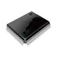
ST92F120V1Q7 STMicroelectronics, ST92F120V1Q7 Datasheet - Page 84

ST92F120V1Q7
Manufacturer Part Number
ST92F120V1Q7
Description
Microcontrollers (MCU) Flash 128K SPI/I2C
Manufacturer
STMicroelectronics
Datasheet
1.ST92F120V9Q7.pdf
(325 pages)
Specifications of ST92F120V1Q7
Data Bus Width
8 bit, 16 bit
Program Memory Type
Flash
Program Memory Size
128 KB
Data Ram Size
4 KB
Interface Type
I2C, SPI
Maximum Clock Frequency
24 MHz
Number Of Programmable I/os
77
Number Of Timers
5
Maximum Operating Temperature
+ 105 C
Mounting Style
SMD/SMT
Package / Case
PQFP-100
Minimum Operating Temperature
- 40 C
On-chip Adc
8 bit, 16 Channel
Lead Free Status / Rohs Status
No
Available stocks
Company
Part Number
Manufacturer
Quantity
Price
Company:
Part Number:
ST92F120V1Q7
Manufacturer:
ST
Quantity:
6 765
Part Number:
ST92F120V1Q7
Manufacturer:
ST
Quantity:
20 000
Part Number:
ST92F120V1Q7C
Manufacturer:
ST
Quantity:
20 000
Company:
Part Number:
ST92F120V1Q7DTR
Manufacturer:
MAXIM
Quantity:
2 854
- Current page: 84 of 325
- Download datasheet (3Mb)
ST92F120 - INTERRUPTS
WAKE-UP / INTERRUPT LINES MANAGEMENT UNIT (Cont’d)
5.11.3.4 NMI Pin Management
On the CPU side, if TLTEV=1 (Top Level Trigger
Event, bit 3 of register R246, page 0) then a rising
edge on the NMI pin will set the TLIP bit (Top Level
Interrupt Pending bit, R230.6). At this point an in-
terrupt request to the CPU is given either if TL-
NM=1 (Top Level Not Maskable bit, R247.7 - once
set it can only be cleared by RESET) or if TLI=1
and IEN=1 (bits R230.5, R230.4).
Assuming that the application uses a non-maska-
ble Top Level Interrupt (TLNM=1): in this case,
whenever a rising edge occurs on the NMI pin, the
related service routine will be executed. To service
further Top Level Interrupt Requests, it is neces-
sary to generate a new rising edge on the external
NMI pin.
The following summarizes some typical cases:
– If the ST9 is in STOP mode and a rising edge on
84/324
9
the NMI pin occurs, the ST9 will exit STOP
mode and the NMI service routine will be exe-
cuted.
– If the ST9 is in Run mode and a rising edge oc-
– If the ST9 is in run mode and a rising edge on
– If the ST9 is in run mode and the NMI pin is high:
curs on the NMI pin: the NMI service routine is
executed and then the ST9 restarts the execu-
tion of the main program. Now, suppose that
the user wants to enter STOP mode with NMI
still at 1. The ST9 will not enter STOP mode
and it will not execute an NMI routine be-
cause there were no transitions on the exter-
nal NMI line.
NMI pin occurs during the STOP bit setting se-
quence: the NMI interrupt will be acknowledged
and the ST9 will not enter STOP mode. At the
end of the NMI routine, the user must re-enter
the sequence: if NMI is still high at the end of the
sequence, the ST9 can not enter STOP mode
(see previous case).
if NMI is forced low just before the third write in-
struction of the STOP bit setting sequence then
the ST9 will enter STOP mode.
Related parts for ST92F120V1Q7
Image
Part Number
Description
Manufacturer
Datasheet
Request
R

Part Number:
Description:
8/16-bit Flash Mcu Family With Ram, Eeprom And J1850 Blpd
Manufacturer:
STMicroelectronics
Datasheet:

Part Number:
Description:
STMicroelectronics [RIPPLE-CARRY BINARY COUNTER/DIVIDERS]
Manufacturer:
STMicroelectronics
Datasheet:

Part Number:
Description:
STMicroelectronics [LIQUID-CRYSTAL DISPLAY DRIVERS]
Manufacturer:
STMicroelectronics
Datasheet:

Part Number:
Description:
BOARD EVAL FOR MEMS SENSORS
Manufacturer:
STMicroelectronics
Datasheet:

Part Number:
Description:
NPN TRANSISTOR POWER MODULE
Manufacturer:
STMicroelectronics
Datasheet:

Part Number:
Description:
TURBOSWITCH ULTRA-FAST HIGH VOLTAGE DIODE
Manufacturer:
STMicroelectronics
Datasheet:

Part Number:
Description:
Manufacturer:
STMicroelectronics
Datasheet:

Part Number:
Description:
DIODE / SCR MODULE
Manufacturer:
STMicroelectronics
Datasheet:

Part Number:
Description:
DIODE / SCR MODULE
Manufacturer:
STMicroelectronics
Datasheet:

Part Number:
Description:
Search -----> STE16N100
Manufacturer:
STMicroelectronics
Datasheet:

Part Number:
Description:
Search ---> STE53NA50
Manufacturer:
STMicroelectronics
Datasheet:

Part Number:
Description:
NPN Transistor Power Module
Manufacturer:
STMicroelectronics
Datasheet:


