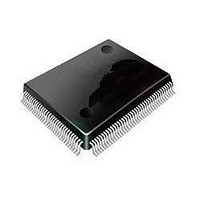
ST92F120V1Q7 STMicroelectronics, ST92F120V1Q7 Datasheet - Page 68

ST92F120V1Q7
Manufacturer Part Number
ST92F120V1Q7
Description
Microcontrollers (MCU) Flash 128K SPI/I2C
Manufacturer
STMicroelectronics
Datasheet
1.ST92F120V9Q7.pdf
(325 pages)
Specifications of ST92F120V1Q7
Data Bus Width
8 bit, 16 bit
Program Memory Type
Flash
Program Memory Size
128 KB
Data Ram Size
4 KB
Interface Type
I2C, SPI
Maximum Clock Frequency
24 MHz
Number Of Programmable I/os
77
Number Of Timers
5
Maximum Operating Temperature
+ 105 C
Mounting Style
SMD/SMT
Package / Case
PQFP-100
Minimum Operating Temperature
- 40 C
On-chip Adc
8 bit, 16 Channel
Lead Free Status / Rohs Status
No
Available stocks
Company
Part Number
Manufacturer
Quantity
Price
Company:
Part Number:
ST92F120V1Q7
Manufacturer:
ST
Quantity:
6 765
Part Number:
ST92F120V1Q7
Manufacturer:
ST
Quantity:
20 000
Part Number:
ST92F120V1Q7C
Manufacturer:
ST
Quantity:
20 000
Company:
Part Number:
ST92F120V1Q7DTR
Manufacturer:
MAXIM
Quantity:
2 854
- Current page: 68 of 325
- Download datasheet (3Mb)
ST92F120 - INTERRUPTS
5.2.2
Routines
The ENCSR bit in the EMR2 register can be used
to select between original ST9 backward compati-
bility mode and ST9+ interrupt management
mode.
ST9 Backward Compatibility Mode (ENCSR= 0)
If ENCSR is reset, the CPU works in original ST9
compatibility mode. For the duration of the inter-
rupt service routine, ISR is used instead of CSR,
and the interrupt stack frame is identical to that of
the original ST9: only the PC and Flags are
pushed.
This avoids saving the CSR on the stack in the
event of an interrupt, thus ensuring a faster inter-
rupt response time.
It is not possible for an interrupt service routine to
perform inter-segment calls or jumps: these in-
structions would update the CSR, which, in this
case, is not used (ISR is used instead). The code
segment size for all interrupt service routines is
thus limited to 64K bytes.
ST9+ mode (ENCSR = 1)
If ENCSR is set, ISR is only used to point to the in-
terrupt vector table and to initialize the CSR at the
beginning of the interrupt service routine: the old
CSR is pushed onto the stack together with the PC
and flags, and CSR is then loaded with the con-
tents of ISR.
In this case, iret will also restore CSR from the
stack. This approach allows interrupt service rou-
tines to access the entire 4 Mbytes of address
space. The drawback is that the interrupt response
time is slightly increased, because of the need to
also save CSR on the stack.
Full compatibility with the original ST9 is lost in this
case, because the interrupt stack frame is differ-
ent.
68/324
9
ENCSR Bit
Mode
Pushed/Popped
Registers
Max. Code Size
for interrupt
service routine
Segment
Within 1 segment
ST9 Compatible
Paging
PC, FLAGR
64KB
0
During
Across segments
PC, FLAGR,
No limit
ST9+
CSR
Interrupt
1
5.3 INTERRUPT PRIORITY LEVELS
The ST9 supports a fully programmable interrupt
priority structure. Nine priority levels are available
to define the channel priority relationships:
– The on-chip peripheral channels and the eight
– The 9th level (Top Level Priority) is reserved for
5.4 PRIORITY LEVEL ARBITRATION
The 3 bits of CPL (Current Priority Level) in the
Central Interrupt Control Register contain the pri-
ority of the currently running program (CPU priori-
ty). CPL is set to 7 (lowest priority) upon reset and
can be modified during program execution either
by software or automatically by hardware accord-
ing to the selected Arbitration Mode.
During every instruction, an arbitration phase
takes place, during which, for every channel capa-
ble of generating an Interrupt, each priority level is
compared to all the other requests (interrupts or
DMA).
If the highest priority request is an interrupt, its
PRL value must be strictly lower (that is, higher pri-
ority) than the CPL value stored in the CICR regis-
ter (R230) in order to be acknowledged. The Top
Level Interrupt overrides every other priority.
5.4.1 Priority level 7 (Lowest)
Interrupt requests at PRL level 7 cannot be ac-
knowledged, as this PRL value (the lowest possi-
ble priority) cannot be strictly lower than the CPL
value. This can be of use in a fully polled interrupt
environment.
5.4.2 Maximum depth of nesting
No more than 8 routines can be nested. If an inter-
rupt routine at level N is being serviced, no other
Interrupts located at level N can interrupt it. This
guarantees a maximum number of 8 nested levels
including the Top Level Interrupt request.
5.4.3 Simultaneous Interrupts
If two or more requests occur at the same time and
at the same priority level, an on-chip daisy chain,
specific to every ST9 version, selects the channel
external interrupt sources can be programmed
within eight priority levels. Each channel has a 3-
bit field, PRL (Priority Level), that defines its pri-
ority level in the range from 0 (highest priority) to
7 (lowest priority).
the Timer/Watchdog or the External Pseudo
Non-Maskable Interrupt. An Interrupt service
routine at this level cannot be interrupted in any
arbitration mode. Its mask can be both maskable
(TLI) or non-maskable (TLNM).
Related parts for ST92F120V1Q7
Image
Part Number
Description
Manufacturer
Datasheet
Request
R

Part Number:
Description:
8/16-bit Flash Mcu Family With Ram, Eeprom And J1850 Blpd
Manufacturer:
STMicroelectronics
Datasheet:

Part Number:
Description:
STMicroelectronics [RIPPLE-CARRY BINARY COUNTER/DIVIDERS]
Manufacturer:
STMicroelectronics
Datasheet:

Part Number:
Description:
STMicroelectronics [LIQUID-CRYSTAL DISPLAY DRIVERS]
Manufacturer:
STMicroelectronics
Datasheet:

Part Number:
Description:
BOARD EVAL FOR MEMS SENSORS
Manufacturer:
STMicroelectronics
Datasheet:

Part Number:
Description:
NPN TRANSISTOR POWER MODULE
Manufacturer:
STMicroelectronics
Datasheet:

Part Number:
Description:
TURBOSWITCH ULTRA-FAST HIGH VOLTAGE DIODE
Manufacturer:
STMicroelectronics
Datasheet:

Part Number:
Description:
Manufacturer:
STMicroelectronics
Datasheet:

Part Number:
Description:
DIODE / SCR MODULE
Manufacturer:
STMicroelectronics
Datasheet:

Part Number:
Description:
DIODE / SCR MODULE
Manufacturer:
STMicroelectronics
Datasheet:

Part Number:
Description:
Search -----> STE16N100
Manufacturer:
STMicroelectronics
Datasheet:

Part Number:
Description:
Search ---> STE53NA50
Manufacturer:
STMicroelectronics
Datasheet:

Part Number:
Description:
NPN Transistor Power Module
Manufacturer:
STMicroelectronics
Datasheet:


