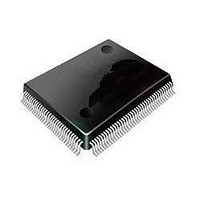
ST92F120V1Q7 STMicroelectronics, ST92F120V1Q7 Datasheet - Page 48

ST92F120V1Q7
Manufacturer Part Number
ST92F120V1Q7
Description
Microcontrollers (MCU) Flash 128K SPI/I2C
Manufacturer
STMicroelectronics
Datasheet
1.ST92F120V9Q7.pdf
(325 pages)
Specifications of ST92F120V1Q7
Data Bus Width
8 bit, 16 bit
Program Memory Type
Flash
Program Memory Size
128 KB
Data Ram Size
4 KB
Interface Type
I2C, SPI
Maximum Clock Frequency
24 MHz
Number Of Programmable I/os
77
Number Of Timers
5
Maximum Operating Temperature
+ 105 C
Mounting Style
SMD/SMT
Package / Case
PQFP-100
Minimum Operating Temperature
- 40 C
On-chip Adc
8 bit, 16 Channel
Lead Free Status / Rohs Status
No
Available stocks
Company
Part Number
Manufacturer
Quantity
Price
Company:
Part Number:
ST92F120V1Q7
Manufacturer:
ST
Quantity:
6 765
Part Number:
ST92F120V1Q7
Manufacturer:
ST
Quantity:
20 000
Part Number:
ST92F120V1Q7C
Manufacturer:
ST
Quantity:
20 000
Company:
Part Number:
ST92F120V1Q7DTR
Manufacturer:
MAXIM
Quantity:
2 854
- Current page: 48 of 325
- Download datasheet (3Mb)
ST92F120 - SINGLE VOLTAGE FLASH & EEPROM
3.5 EEPROM
3.5.1 Hardware EEPROM Emulation
Note: This section provides general information
only. Users do not have to be concerned with the
hardware EEPROM emulation.
The last 256 bytes of the two EEPROM dedicated
sectors (229000h to 2290FFh for sector E0 and
22D000h to 22D0FFh for sector E1) are reserved
for the Non Volatile pointers used for the hardware
Emulation.
When the EEPROM is directly addressed through
the addresses 220000h to 2203FFh, a Hardware
Emulation mechanism is automatically activated,
so avoiding the user having to manage the Non
Volatile pointers that are used to map the EEP-
Figure 23. Segment 22h Structure (Example for 128K Flash device)
48/324
9
229000h
228000h
228400h
228800h
228C00h
220000h
2203FFh
EEPROM sector E0
HW emulated EEPROM
Non Volatile Status
256 byte
Page 62 - 16 byte
Page 63 - 16 byte
Page 62 - 16 byte
Page 63 - 16 byte
Page 62 - 16 byte
Page 63 - 16 byte
Page 62 - 16 byte
Page 63 - 16 byte
64 pages
1 Kbyte
Page 0 - 16 byte
Page 1 - 16 byte
Page 0 - 16 byte
Page 1 - 16 byte
Page 0 - 16 byte
Page 1 - 16 byte
Page 0 - 16 byte
Page 1 - 16 byte
Page 2 to 61
Page 2 to 61
Page 2 to 61
Page 2 to 61
224000h
22D000h
22C000h
22C400h
22C800h
22CC00h
ROM inside the two dedicated Flash sectors E0
and E1.
The structure of the hardware emulation is shown
in
Each one of the two EEPROM dedicated Flash
sectors E0 and E1 is divided in 4 blocks of the
same size of the EEPROM to emulate (1Kbyte
max).
Each one of the 4 blocks is then divided in up to 64
pages of 16 bytes, the size of the available RAM
buffer.
The RAM buffer is used internally to temporarily
store the new content of the page to update, dur-
ing the Page Program operation (both in Flash and
in EEPROM).
Figure
23.
EEPROM sector E1
FCR, ECR, FESR1-0 - 4 byte
User Registers
Page buffer - 16 byte
Non Volatile Status
RAM buffer
256 byte
Page 62 - 16 byte
Page 63 - 16 byte
Page 62 - 16 byte
Page 63 - 16 byte
Page 62 - 16 byte
Page 63 - 16 byte
Page 62 - 16 byte
Page 63 - 16 byte
Page 0 - 16 byte
Page 1 - 16 byte
Page 0 - 16 byte
Page 1 - 16 byte
Page 0 - 16 byte
Page 1 - 16 byte
Page 0 - 16 byte
Page 1 - 16 byte
Page 2 to 61
Page 2 to 61
Page 2 to 61
Page 2 to 61
Related parts for ST92F120V1Q7
Image
Part Number
Description
Manufacturer
Datasheet
Request
R

Part Number:
Description:
8/16-bit Flash Mcu Family With Ram, Eeprom And J1850 Blpd
Manufacturer:
STMicroelectronics
Datasheet:

Part Number:
Description:
STMicroelectronics [RIPPLE-CARRY BINARY COUNTER/DIVIDERS]
Manufacturer:
STMicroelectronics
Datasheet:

Part Number:
Description:
STMicroelectronics [LIQUID-CRYSTAL DISPLAY DRIVERS]
Manufacturer:
STMicroelectronics
Datasheet:

Part Number:
Description:
BOARD EVAL FOR MEMS SENSORS
Manufacturer:
STMicroelectronics
Datasheet:

Part Number:
Description:
NPN TRANSISTOR POWER MODULE
Manufacturer:
STMicroelectronics
Datasheet:

Part Number:
Description:
TURBOSWITCH ULTRA-FAST HIGH VOLTAGE DIODE
Manufacturer:
STMicroelectronics
Datasheet:

Part Number:
Description:
Manufacturer:
STMicroelectronics
Datasheet:

Part Number:
Description:
DIODE / SCR MODULE
Manufacturer:
STMicroelectronics
Datasheet:

Part Number:
Description:
DIODE / SCR MODULE
Manufacturer:
STMicroelectronics
Datasheet:

Part Number:
Description:
Search -----> STE16N100
Manufacturer:
STMicroelectronics
Datasheet:

Part Number:
Description:
Search ---> STE53NA50
Manufacturer:
STMicroelectronics
Datasheet:

Part Number:
Description:
NPN Transistor Power Module
Manufacturer:
STMicroelectronics
Datasheet:


