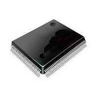
ST92F120V1Q7 STMicroelectronics, ST92F120V1Q7 Datasheet - Page 41

ST92F120V1Q7
Manufacturer Part Number
ST92F120V1Q7
Description
Microcontrollers (MCU) Flash 128K SPI/I2C
Manufacturer
STMicroelectronics
Datasheet
1.ST92F120V9Q7.pdf
(325 pages)
Specifications of ST92F120V1Q7
Data Bus Width
8 bit, 16 bit
Program Memory Type
Flash
Program Memory Size
128 KB
Data Ram Size
4 KB
Interface Type
I2C, SPI
Maximum Clock Frequency
24 MHz
Number Of Programmable I/os
77
Number Of Timers
5
Maximum Operating Temperature
+ 105 C
Mounting Style
SMD/SMT
Package / Case
PQFP-100
Minimum Operating Temperature
- 40 C
On-chip Adc
8 bit, 16 Channel
Lead Free Status / Rohs Status
No
Available stocks
Company
Part Number
Manufacturer
Quantity
Price
Company:
Part Number:
ST92F120V1Q7
Manufacturer:
ST
Quantity:
6 765
Part Number:
ST92F120V1Q7
Manufacturer:
ST
Quantity:
20 000
Part Number:
ST92F120V1Q7C
Manufacturer:
ST
Quantity:
20 000
Company:
Part Number:
ST92F120V1Q7DTR
Manufacturer:
MAXIM
Quantity:
2 854
- Current page: 41 of 325
- Download datasheet (3Mb)
FUNCTIONAL DESCRIPTION (Cont’d)
3.2.3 Operation
The memory has a register interface mapped in
memory space (segment 22h). All operations are
enabled through the FCR (Flash Control Register)
ECR (EEPROM Control Register).
All operations on the Flash must be executed from
another memory (internal RAM, EEPROM, exter-
nal memory).
Flash (including TestFlash) and EEPROM have
duplicated sense amplifiers, so that one can be
read while the other is written. However simultane-
ous Flash and EEPROM write operations are for-
bidden.
An interrupt can be generated at the end of a
Flash or an EEPROM write operation: this inter-
rupt is multiplexed with an external interrupt EX-
TINTx (device dependent) to generate an interrupt
INTx.
The status of a write operation inside the Flash
and the EEPROM memories can be monitored
through the FESR[1:0] registers.
ST92F120 - SINGLE VOLTAGE FLASH & EEPROM
Control and Status registers are mapped in mem-
ory (segment 22h), as shown in the following fig-
ure.
Figure 22. Control and Status Register Map
During a write operation, if the power supply drops
or the RESET pin is activated, the write operation
is immediately interrupted. In this case the user
must repeat the last write operation following pow-
er on or reset.
224003h
224000h
224001h
224002h
Register Interface
ECR
FCR
FESR0
FESR1
41/324
9
Related parts for ST92F120V1Q7
Image
Part Number
Description
Manufacturer
Datasheet
Request
R

Part Number:
Description:
8/16-bit Flash Mcu Family With Ram, Eeprom And J1850 Blpd
Manufacturer:
STMicroelectronics
Datasheet:

Part Number:
Description:
STMicroelectronics [RIPPLE-CARRY BINARY COUNTER/DIVIDERS]
Manufacturer:
STMicroelectronics
Datasheet:

Part Number:
Description:
STMicroelectronics [LIQUID-CRYSTAL DISPLAY DRIVERS]
Manufacturer:
STMicroelectronics
Datasheet:

Part Number:
Description:
BOARD EVAL FOR MEMS SENSORS
Manufacturer:
STMicroelectronics
Datasheet:

Part Number:
Description:
NPN TRANSISTOR POWER MODULE
Manufacturer:
STMicroelectronics
Datasheet:

Part Number:
Description:
TURBOSWITCH ULTRA-FAST HIGH VOLTAGE DIODE
Manufacturer:
STMicroelectronics
Datasheet:

Part Number:
Description:
Manufacturer:
STMicroelectronics
Datasheet:

Part Number:
Description:
DIODE / SCR MODULE
Manufacturer:
STMicroelectronics
Datasheet:

Part Number:
Description:
DIODE / SCR MODULE
Manufacturer:
STMicroelectronics
Datasheet:

Part Number:
Description:
Search -----> STE16N100
Manufacturer:
STMicroelectronics
Datasheet:

Part Number:
Description:
Search ---> STE53NA50
Manufacturer:
STMicroelectronics
Datasheet:

Part Number:
Description:
NPN Transistor Power Module
Manufacturer:
STMicroelectronics
Datasheet:


