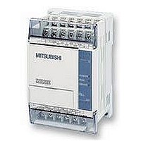
FX1S-30MR-ES/UL MITSUBISHI, FX1S-30MR-ES/UL Datasheet - Page 83

FX1S-30MR-ES/UL
Manufacturer Part Number
FX1S-30MR-ES/UL
Description
PLC, 16 IN, 14 RELAY OUT, 110V/2
Manufacturer
MITSUBISHI
Datasheet
1.FX1S-30MR-ESUL.pdf
(380 pages)
Specifications of FX1S-30MR-ES/UL
No. Of Analogue Inputs
16
No. Of Analogue Outputs
14
Ip/nema Rating
IP10
Approval Bodies
CE, CUL, UL
External Depth
49mm
External Length / Height
90mm
External Width
60mm
Mounting Type
Panel
- Current page: 83 of 380
- Download datasheet (7Mb)
4.4.4
FX Series Programmable Controllers
Annunciator Flags
Some state flags can be used as outputs for external diagnosis (called annunciation) when
certain applied instructions are used. These instructions are;
ANS function 46: ANnunciator Set - see page 5-47
ANR function 47: ANnunciator Reset - see page 5-47
When the annunciator function is used the controlled state flags are in the range S900 to S999
(100 points). By programming an external diagnosis circuit as shown below, and monitoring
special data register D8049, the lowest activated state from the annunciator range will be
displayed.
Each of the states can be assigned to signify an error or fault condition. As a fault occurs the
associated state is driven ON. If more than one fault occurs simultaneously, the lowest fault
number will be displayed. When the active fault is cleared the next lowest fault will then be
processed.
This means that for a correctly prioritized diagnostic system the most dangerous or damaging
faults should activate the lowest state flags, from the annunciator range. All state flags used for
the annunciator function fall in the range of battery backed/ latched state registers.
Monitoring is enabled by driving special auxiliary
relay M8049 ON.
State S900 is activated if input X0 is not driven
within one second after the output Y0 has been
turned ON.
State S901 is activated when both inputs X1 and
X2 are OFF for more than two seconds.
If the cycle time of the controlled machine is less
than ten seconds, and input X3 stays ON, state
S902 will be set ON if X4 is not activated within
this machine cycle time.
If any state from S900 to S999 is activated, i.e.
ON, special auxiliary relay M8048 is activated to
turn on failure indicator output Y10.
The states activated by the users error / failure
diagnosis detection program, are turned OFF by
activating input X5. Each time X5 is activated, the
active annunciator states are reset in ascending
order of state numbers.
M8000
M8048
Y0
X1
X3
X5
X0
X2
X4
ANS
ANS
ANS
FNC46
FNC46
FNC46
T2
T0
T1
Devices in Detail 4
K100
K10
K20
ANR (P)
4-9
M8049
Y10
S900
S901
S902
FNC47
Related parts for FX1S-30MR-ES/UL
Image
Part Number
Description
Manufacturer
Datasheet
Request
R

Part Number:
Description:
MITSUBISHI IGBT MODULES
Manufacturer:
MITSUBISHI
Datasheet:

Part Number:
Description:
MITSUBISHI INTELLIGENT POWER MODULES
Manufacturer:
MITSUBISHI
Datasheet:

Part Number:
Description:
TRANSFER-MOLD TYPE INSULATED TYPE
Manufacturer:
MITSUBISHI
Datasheet:

Part Number:
Description:
Manufacturer:
MITSUBISHI
Datasheet:

Part Number:
Description:
30A intelligent power module for flat-base type
Manufacturer:
MITSUBISHI
Datasheet:

Part Number:
Description:
15A - transistor module for medium power switching use, insulated type
Manufacturer:
MITSUBISHI
Datasheet:

Part Number:
Description:
5A power module for transfer-mold type insulated type
Manufacturer:
MITSUBISHI
Datasheet:

Part Number:
Description:
30A intelligent power module for flat-base type
Manufacturer:
MITSUBISHI
Datasheet:

Part Number:
Description:
TRANSFER-MOLD TYPE INSULATED TYPE
Manufacturer:
MITSUBISHI
Datasheet:

Part Number:
Description:
TRANSFER-MOLD TYPE INSULATED TYPE
Manufacturer:
MITSUBISHI
Datasheet:

Part Number:
Description:
20A - transistor module for medium power switching use, insulated type
Manufacturer:
MITSUBISHI
Datasheet:

Part Number:
Description:
20A - transistor module for medium power switching use, insulated type
Manufacturer:
MITSUBISHI
Datasheet:


