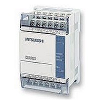
FX1S-30MR-ES/UL MITSUBISHI, FX1S-30MR-ES/UL Datasheet - Page 310

FX1S-30MR-ES/UL
Manufacturer Part Number
FX1S-30MR-ES/UL
Description
PLC, 16 IN, 14 RELAY OUT, 110V/2
Manufacturer
MITSUBISHI
Datasheet
1.FX1S-30MR-ESUL.pdf
(380 pages)
Specifications of FX1S-30MR-ES/UL
No. Of Analogue Inputs
16
No. Of Analogue Outputs
14
Ip/nema Rating
IP10
Approval Bodies
CE, CUL, UL
External Depth
49mm
External Length / Height
90mm
External Width
60mm
Mounting Type
Panel
- Current page: 310 of 380
- Download datasheet (7Mb)
FX Series Programmable Controllers
•
•
•
•
•
•
•
•
•
•
•
•
•
•
•
1:
2:
3:
4:
5:
6:
7:
8:
9:
10:
11:
12:
13:
14:
15:
These instructions require NO preliminary contact devices such as LD, AND, OR etc.
Where “n” is referred to this identifies the quantity of registers to be manipulated.
“n” can be equal or less than 512.
Where “n” is referred to this identifies the quantity of bit devices to be manipulated.
“n” can be equal or less than selected operating mode, i.e. if 32 bit mode is selected then “n” can
have a value equal or less than 32.
Where "n" is referred to this identifies the quantity of bit devices to be manipulated.
When an FX1N PLC is used "n" can be equal or less than 1536.
However, when an FX1S controller is used "n" can be equal or less than 512.
Where "n" is referred to this identifies the quantity devices to be manipulated. "n" can have any value
taken from the range 2 through 512.
Where "n" is referred to this identifies the range of devices to be reset. The device type being reset is
identified by the device letter in brackets in the '16/32 bit' column.
Where "n" is referred to this identifies the number of devices the mean is to be calculated from. The
value of "n" can be taken from the range 1 through 64.
Where "n" is referred to this identifies the range of devices to be refreshed. The value of "n" is always
specified in units of 8, i.e 8, 16, 24.....128. The maximum allowable range is dependent on the
number of available inputs/outputs.
Where "n" is referred to this identifies the time setting for the input filters operation.
"n" can be selected from the range 0 through to 60 msec.
There are limits to the total combined use of these instructions. For FX
no more than 4 simultaneously active instructions. However, FX
simultaneously active instructions.
Where "n" is referred to this identifies the number of output points. "n" may have a value equal or less
than 64.
Where "n" is referred to this identifies the number of words read or written FROM/TO the special
function blocks.
Where "n" is referred to this identifies the number of octal (8 bit) words read or written when two FX
PLC’s are involved in a parallel running function.
Where "n" is referred to this identifies the number of elements in a stack, for 16 bit operation n has a
maximum of 256. However, for 32 bit operation n has a maximum of 128.
Where "m1" is referred to this identifies the number of elements in the data table.
Values of m1 are taken from the range 1 to 32. For a the SORT instruction to completely process the
data table the SORT instruction will be processed m1 times.
Execution Times And Instructional Hierarchy 7
1S
2N
and FX
and FX
1N
2N
7-10
there should be
c can have 6
Related parts for FX1S-30MR-ES/UL
Image
Part Number
Description
Manufacturer
Datasheet
Request
R

Part Number:
Description:
MITSUBISHI IGBT MODULES
Manufacturer:
MITSUBISHI
Datasheet:

Part Number:
Description:
MITSUBISHI INTELLIGENT POWER MODULES
Manufacturer:
MITSUBISHI
Datasheet:

Part Number:
Description:
TRANSFER-MOLD TYPE INSULATED TYPE
Manufacturer:
MITSUBISHI
Datasheet:

Part Number:
Description:
Manufacturer:
MITSUBISHI
Datasheet:

Part Number:
Description:
30A intelligent power module for flat-base type
Manufacturer:
MITSUBISHI
Datasheet:

Part Number:
Description:
15A - transistor module for medium power switching use, insulated type
Manufacturer:
MITSUBISHI
Datasheet:

Part Number:
Description:
5A power module for transfer-mold type insulated type
Manufacturer:
MITSUBISHI
Datasheet:

Part Number:
Description:
30A intelligent power module for flat-base type
Manufacturer:
MITSUBISHI
Datasheet:

Part Number:
Description:
TRANSFER-MOLD TYPE INSULATED TYPE
Manufacturer:
MITSUBISHI
Datasheet:

Part Number:
Description:
TRANSFER-MOLD TYPE INSULATED TYPE
Manufacturer:
MITSUBISHI
Datasheet:

Part Number:
Description:
20A - transistor module for medium power switching use, insulated type
Manufacturer:
MITSUBISHI
Datasheet:

Part Number:
Description:
20A - transistor module for medium power switching use, insulated type
Manufacturer:
MITSUBISHI
Datasheet:


