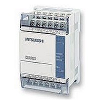
FX1S-30MR-ES/UL MITSUBISHI, FX1S-30MR-ES/UL Datasheet - Page 177

FX1S-30MR-ES/UL
Manufacturer Part Number
FX1S-30MR-ES/UL
Description
PLC, 16 IN, 14 RELAY OUT, 110V/2
Manufacturer
MITSUBISHI
Datasheet
1.FX1S-30MR-ESUL.pdf
(380 pages)
Specifications of FX1S-30MR-ES/UL
No. Of Analogue Inputs
16
No. Of Analogue Outputs
14
Ip/nema Rating
IP10
Approval Bodies
CE, CUL, UL
External Depth
49mm
External Length / Height
90mm
External Width
60mm
Mounting Type
Panel
- Current page: 177 of 380
- Download datasheet (7Mb)
5.6.4
FX Series Programmable Controlers
f) Because this instruction uses a series of
g) Example Operation
HSCS (FNC 53)
as the destination (D)is set ON. The example above shows that Y10 would be set ON only
when C255’s value stepped from 99-100 OR 101-100. If the counters current value was forced
to equal 100, output Y10 would NOT be set ON.
HSCS
FNC 53
(
counter set)
High
Mnemonic
Notice how the resulting matrix-table does not use any of the
state S or auxiliary M relays are used as the storage medium.
multiplexed signals it requires a certain amount of
‘hard wiring’ to operate. The example wiring
diagram to the right depicts the circuit used if the
previous example instruction was programmed. As
a general precaution to aid successful operation
diodes should be places after each input device
(see diagram opposite). These should have a
rating of 0.1A, 50V.
When output Y20 is ON only those inputs in the
first bank are read. These results are then stored;
in this example, auxiliary coils M30 to M37. The
second step involves Y20 going OFF and Y21
coming ON. This time only inputs in the second
bank are read. These results are stored in devices
M40 to M47. The last step of this example has Y21
going OFF and Y22 coming ON. This then allows all of the inputs in the third bank to be
read and stored in devices M50 to M57. The processing of this instruction example would
take 20
speed
3 = 60msec.
Sets the selected
output when the
specified high
speed counter
value equals the
test value
Function
K, H,
KnX, KnY,
KnM, KnS,
T, C, D, V, Z
S
1
Operation :
The HSCS set, compares the current value of the
selected high speed counter (S
value (S
changes to a value equal to S
C
Note:
C = 235 to 254,
or available
high speed
counters
Operands
S
1
2
). When the counters current value
Y, M, S
Interrupt point-
ers
I010 to I060
can be set.
8 and
n
1
Applied Instructions 5
the device specified
2
9 bit devices when
)against a selected
DHSCS:
13 steps
Program steps
5-55
Related parts for FX1S-30MR-ES/UL
Image
Part Number
Description
Manufacturer
Datasheet
Request
R

Part Number:
Description:
MITSUBISHI IGBT MODULES
Manufacturer:
MITSUBISHI
Datasheet:

Part Number:
Description:
MITSUBISHI INTELLIGENT POWER MODULES
Manufacturer:
MITSUBISHI
Datasheet:

Part Number:
Description:
TRANSFER-MOLD TYPE INSULATED TYPE
Manufacturer:
MITSUBISHI
Datasheet:

Part Number:
Description:
Manufacturer:
MITSUBISHI
Datasheet:

Part Number:
Description:
30A intelligent power module for flat-base type
Manufacturer:
MITSUBISHI
Datasheet:

Part Number:
Description:
15A - transistor module for medium power switching use, insulated type
Manufacturer:
MITSUBISHI
Datasheet:

Part Number:
Description:
5A power module for transfer-mold type insulated type
Manufacturer:
MITSUBISHI
Datasheet:

Part Number:
Description:
30A intelligent power module for flat-base type
Manufacturer:
MITSUBISHI
Datasheet:

Part Number:
Description:
TRANSFER-MOLD TYPE INSULATED TYPE
Manufacturer:
MITSUBISHI
Datasheet:

Part Number:
Description:
TRANSFER-MOLD TYPE INSULATED TYPE
Manufacturer:
MITSUBISHI
Datasheet:

Part Number:
Description:
20A - transistor module for medium power switching use, insulated type
Manufacturer:
MITSUBISHI
Datasheet:

Part Number:
Description:
20A - transistor module for medium power switching use, insulated type
Manufacturer:
MITSUBISHI
Datasheet:


