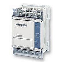
FX1S-30MR-ES/UL MITSUBISHI, FX1S-30MR-ES/UL Datasheet - Page 195

FX1S-30MR-ES/UL
Manufacturer Part Number
FX1S-30MR-ES/UL
Description
PLC, 16 IN, 14 RELAY OUT, 110V/2
Manufacturer
MITSUBISHI
Datasheet
1.FX1S-30MR-ESUL.pdf
(380 pages)
Specifications of FX1S-30MR-ES/UL
No. Of Analogue Inputs
16
No. Of Analogue Outputs
14
Ip/nema Rating
IP10
Approval Bodies
CE, CUL, UL
External Depth
49mm
External Length / Height
90mm
External Width
60mm
Mounting Type
Panel
- Current page: 195 of 380
- Download datasheet (7Mb)
5.7.7
5.7.8
FX Series Programmable Controlers
ALT (FNC 66)
RAMP (FNC 67)
ALT
FNC 66
(Alternate
state)
RAMP
FNC 67
(Ramp vari-
able value)
Mnemonic
Mnemonic
The status of the
assigned device
is inverted on
every operation of
the instruction
Ramps a device
from one value to
another in the
specified number
of steps
Function
Function
Y, M, S
D
Note:
Device D uses two consecutive
registers identified as D and D+1
these are read only devices.
S
1
Operation:
The sta tus o f the destination device (D) is
a l t e r n a t e d o n e v e r y o p e r a t i o n o f t h e A LT
instruction.
This means the status of each bit device will flip-
flop between ON and OFF. This will occur on every
program scan unless a pulse modifier or a program
interlock is used.
The ALT instruction is ideal for switching between
two modes of operation e.g. start and stop, on and
off etc.
Operation:
The RAMP instruction varies a current value (D)
between the data limits set by the user (S1and S2).
The ‘journey’ between these extreme limits takes n
program scans. The current scan number is stored
in device D+1. Once the current value of D equals
the set value of S2the execution complete flag
M8029 is set ON.
The RAMP instruction can vary both increasing
and decreasing differences between S1and S2.
S
2
Operands
Operands
D
D
K, H
Note:
n= 1 to
32,767
n
Applied Instructions 5
ALT, ALTP:
3 steps
RAMP:
9 steps
Program steps
Program steps
5-73
Related parts for FX1S-30MR-ES/UL
Image
Part Number
Description
Manufacturer
Datasheet
Request
R

Part Number:
Description:
MITSUBISHI IGBT MODULES
Manufacturer:
MITSUBISHI
Datasheet:

Part Number:
Description:
MITSUBISHI INTELLIGENT POWER MODULES
Manufacturer:
MITSUBISHI
Datasheet:

Part Number:
Description:
TRANSFER-MOLD TYPE INSULATED TYPE
Manufacturer:
MITSUBISHI
Datasheet:

Part Number:
Description:
Manufacturer:
MITSUBISHI
Datasheet:

Part Number:
Description:
30A intelligent power module for flat-base type
Manufacturer:
MITSUBISHI
Datasheet:

Part Number:
Description:
15A - transistor module for medium power switching use, insulated type
Manufacturer:
MITSUBISHI
Datasheet:

Part Number:
Description:
5A power module for transfer-mold type insulated type
Manufacturer:
MITSUBISHI
Datasheet:

Part Number:
Description:
30A intelligent power module for flat-base type
Manufacturer:
MITSUBISHI
Datasheet:

Part Number:
Description:
TRANSFER-MOLD TYPE INSULATED TYPE
Manufacturer:
MITSUBISHI
Datasheet:

Part Number:
Description:
TRANSFER-MOLD TYPE INSULATED TYPE
Manufacturer:
MITSUBISHI
Datasheet:

Part Number:
Description:
20A - transistor module for medium power switching use, insulated type
Manufacturer:
MITSUBISHI
Datasheet:

Part Number:
Description:
20A - transistor module for medium power switching use, insulated type
Manufacturer:
MITSUBISHI
Datasheet:


