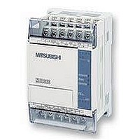
FX1S-30MR-ES/UL MITSUBISHI, FX1S-30MR-ES/UL Datasheet - Page 183

FX1S-30MR-ES/UL
Manufacturer Part Number
FX1S-30MR-ES/UL
Description
PLC, 16 IN, 14 RELAY OUT, 110V/2
Manufacturer
MITSUBISHI
Datasheet
1.FX1S-30MR-ESUL.pdf
(380 pages)
Specifications of FX1S-30MR-ES/UL
No. Of Analogue Inputs
16
No. Of Analogue Outputs
14
Ip/nema Rating
IP10
Approval Bodies
CE, CUL, UL
External Depth
49mm
External Length / Height
90mm
External Width
60mm
Mounting Type
Panel
- Current page: 183 of 380
- Download datasheet (7Mb)
5.6.8
FX Series Programmable Controlers
changing to the new instance.
It is possible to use subroutines or other such programming techniques to isolate different
instances of this instructions. In this case, the current instruction must be deactivated before
PLSY (FNC 57)
Points to note:
a) FX
b) The maximum number of pulses: 16 bit operation: 1 to 32,767 pulses, 32 bit operation: 1 to
c) A single pulse is described as having a 50% duty cycle. This means it is ON for 50% of the
d) The data in operands S
e) Two FNC 57 (PLSY) can be used at the same time in a program to output pulses to Y000
f) Because of the nature of the high speed output, transistor output units should be used with
g) FX
h) FX
PLSY
FNC 57
(Pulse Y
output)
Mnemonic
(32-bit operation). FX
2,147,483,647 pulses.
Note: special auxiliary coil M8029 is turned ON when the specified number of pulses has
been completed. The pulse count and completion flag (M8029) are reset when the PLSY
instruction is de-energized. If “0" (zero) is specified the PLSY instruction will continue
generating pulses for as long as the instruction is energized.
pulse and consequently OFF for the remaining 50% of the pulse. The actual output is
controlled by interrupt handling, i.e. the output cycle is NOT affected by the scan time of the
program.
in S
instruction has been reset by removal of the drive contact.
and Y001 respectively. Or, only one FNC 57 PLSY and one FNC 59 PLSR can be used
together in the active program at once, again outputting independent pulses to Y000 and
Y001.
this instruction. Relay outputs will suffer from a greatly reduced life and will cause false
outputs to occur due to the mechanical ‘bounce’ of the contacts.
To ensure a ‘clean’ output signal when using transistor units, the load current should be
200mA or higher. It may be found that ‘pull up’ resistors will be required.
source device S
and D8141, and the number of output pulses output to Y1 using devices D8142 and D8143.
The total number of pulses output can be monitored using D8136 and D8137.
1S
2N
2N
2
/FX
and FX
and FX
will not become effective until the current operation has been completed, i.e. the
1N
users may use frequencies of 1 to 132,767Hz (16-bit operation) and 1 to 100kHz
Outputs a
specified number
of pulses at a set
frequency
2NC
2NC
Function
1
units can use the HSZ (FNC 55) instruction with the PLSY instruction when
units can monitor the number of pulses output to Y0 usingdevices D8140
is set to D8132. Please see page 5-59 for more details.
2N
/FX
1
and S
2NC
K, H,
KnX, KnY,
KnM, KnS,
T, C, D, V, Z
users may use frequencies of 2 to 20kHz.
2
may be changed during execution. However, the new data
S
1
Operation :
A specified quantity of pulses S
devic e D at a spe cifie d fre quency S
instruction is used in situations where the quantity
of outputs is of primary concern.
S
2
Operands
Y
Note:
Y000 or Y001 only
D
Applied Instructions 5
.
2
PLSY:
7 steps
DPLSY:
13steps
is output through
Program steps
5-61
1
. Th is
Related parts for FX1S-30MR-ES/UL
Image
Part Number
Description
Manufacturer
Datasheet
Request
R

Part Number:
Description:
MITSUBISHI IGBT MODULES
Manufacturer:
MITSUBISHI
Datasheet:

Part Number:
Description:
MITSUBISHI INTELLIGENT POWER MODULES
Manufacturer:
MITSUBISHI
Datasheet:

Part Number:
Description:
TRANSFER-MOLD TYPE INSULATED TYPE
Manufacturer:
MITSUBISHI
Datasheet:

Part Number:
Description:
Manufacturer:
MITSUBISHI
Datasheet:

Part Number:
Description:
30A intelligent power module for flat-base type
Manufacturer:
MITSUBISHI
Datasheet:

Part Number:
Description:
15A - transistor module for medium power switching use, insulated type
Manufacturer:
MITSUBISHI
Datasheet:

Part Number:
Description:
5A power module for transfer-mold type insulated type
Manufacturer:
MITSUBISHI
Datasheet:

Part Number:
Description:
30A intelligent power module for flat-base type
Manufacturer:
MITSUBISHI
Datasheet:

Part Number:
Description:
TRANSFER-MOLD TYPE INSULATED TYPE
Manufacturer:
MITSUBISHI
Datasheet:

Part Number:
Description:
TRANSFER-MOLD TYPE INSULATED TYPE
Manufacturer:
MITSUBISHI
Datasheet:

Part Number:
Description:
20A - transistor module for medium power switching use, insulated type
Manufacturer:
MITSUBISHI
Datasheet:

Part Number:
Description:
20A - transistor module for medium power switching use, insulated type
Manufacturer:
MITSUBISHI
Datasheet:


