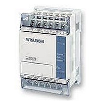
FX1S-30MR-ES/UL MITSUBISHI, FX1S-30MR-ES/UL Datasheet - Page 190

FX1S-30MR-ES/UL
Manufacturer Part Number
FX1S-30MR-ES/UL
Description
PLC, 16 IN, 14 RELAY OUT, 110V/2
Manufacturer
MITSUBISHI
Datasheet
1.FX1S-30MR-ESUL.pdf
(380 pages)
Specifications of FX1S-30MR-ES/UL
No. Of Analogue Inputs
16
No. Of Analogue Outputs
14
Ip/nema Rating
IP10
Approval Bodies
CE, CUL, UL
External Depth
49mm
External Length / Height
90mm
External Width
60mm
Mounting Type
Panel
- Current page: 190 of 380
- Download datasheet (7Mb)
FX Series Programmable Controlers
e) The available operating modes are split into two main groups, manual and automatic. There
Manual (selected by device S+0)- Power supply to individual loads is turned ON and OFF by
using a separately provided means, often additional push buttons.
Zero Return (selected by device S+1) -Actuators are returned to their initial positions when the
Zero input (S+5) is given.
One Step (selected by device S+2)- The controlled sequence operates automatically but will
only proceed to each new step when the start input (S+6) is given.
One Cycle (selected by device S+3) - The controlled actuators are operated for one operation
cycle. After the cycle has been completed, the actuators stop at their ‘zero’ positions. The
cycle is started after a ‘start’ input (S+6) has been given.
A cycle which is currently being processed can be stopped at any time by activating the ‘stop’
input (S+7). To restart the sequence from the currently ‘paused’ position the start input must be
given once more.
Automatic (selected by device S+4)-Fully automatic operation is possible in this mode. The
programmed cycle is executed repeatedly when the ‘start’ input (S+6) is given. The currently
operating cycle will not stop immediately when the ‘stop’ input (S+7)is given.
The current operation will proceed to then end of the current cycle and then stop its operation.
Note: Start, stop and zero inputs are often given by additional, manually operated push
buttons.
Please note that the ‘stop’ input is only a program stop signal. It cannot be used as a
replacement for an ‘Emergency stop’ push button. All safety, ‘Emergency stop’ devices should
be hardwired systems which will effectively isolate the machine from operation and external
power supplies. Please refer to local and national standards for applicable safety practices.
are sub-modes to these groups. Their operation is defined as:
Manual
Automatic
Applied Instructions 5
5-68
Related parts for FX1S-30MR-ES/UL
Image
Part Number
Description
Manufacturer
Datasheet
Request
R

Part Number:
Description:
MITSUBISHI IGBT MODULES
Manufacturer:
MITSUBISHI
Datasheet:

Part Number:
Description:
MITSUBISHI INTELLIGENT POWER MODULES
Manufacturer:
MITSUBISHI
Datasheet:

Part Number:
Description:
TRANSFER-MOLD TYPE INSULATED TYPE
Manufacturer:
MITSUBISHI
Datasheet:

Part Number:
Description:
Manufacturer:
MITSUBISHI
Datasheet:

Part Number:
Description:
30A intelligent power module for flat-base type
Manufacturer:
MITSUBISHI
Datasheet:

Part Number:
Description:
15A - transistor module for medium power switching use, insulated type
Manufacturer:
MITSUBISHI
Datasheet:

Part Number:
Description:
5A power module for transfer-mold type insulated type
Manufacturer:
MITSUBISHI
Datasheet:

Part Number:
Description:
30A intelligent power module for flat-base type
Manufacturer:
MITSUBISHI
Datasheet:

Part Number:
Description:
TRANSFER-MOLD TYPE INSULATED TYPE
Manufacturer:
MITSUBISHI
Datasheet:

Part Number:
Description:
TRANSFER-MOLD TYPE INSULATED TYPE
Manufacturer:
MITSUBISHI
Datasheet:

Part Number:
Description:
20A - transistor module for medium power switching use, insulated type
Manufacturer:
MITSUBISHI
Datasheet:

Part Number:
Description:
20A - transistor module for medium power switching use, insulated type
Manufacturer:
MITSUBISHI
Datasheet:


